Circuit and method for controlling RGB LED color balance using a variable boosted supply voltage

Inactive Publication Date: 2010-12-16
AERIELLE TECH
View PDF3 Cites 13 Cited by
  • Summary
  • Abstract
  • Description
  • Claims
  • Application Information

AI Technical Summary

Benefits of technology

[0014]It is principal advantage of the present invention to remove the need of costly boost regulators by replacing such regulators with two Schottky diodes and two small ceramic capacitors for each LED to be driven. These added components form a charge pump network.
[0015]It is another advantage of the present invention to provide a circuit able to vary the drive to a corresponding LED by adjusting the frequency or duty cycle of the pulse width modulated signal.
[0016]It is yet another advantage of the present invention to gang three of above-referenced networks together and to properly control the intensity of each LED, thereby controlling the color balance.
[0017]It is still another advantage of the present invention to increase the drive current available in an LED-containing consumer electronic devi

Problems solved by technology

However, the green and blue LEDs may require a higher voltage than 3.3V; otherwise, they may fail to illuminate.
However, adding a boost regulator for this single purpose adds substantially to the costs of materials for low-cost consumer el

Method used


Image

  • Circuit and method for controlling RGB LED color balance using a variable boosted supply voltage
  • Circuit and method for controlling RGB LED color balance using a variable boosted supply voltage
  • Circuit and method for controlling RGB LED color balance using a variable boosted supply voltage

Examples


Example

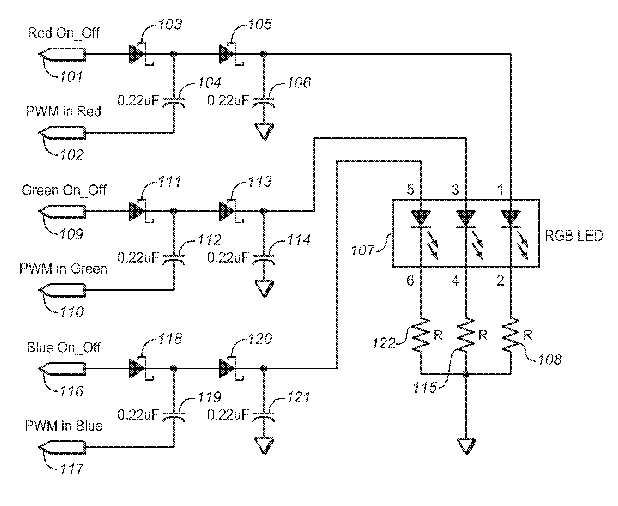
[0031]Referring first to FIG. 1, this schematic diagram shows how the interface of a microprocessor may be used to drive the RGB LED array using three separate charge pumps. The microprocessor drives pins 101 and 102 in order to achieve the boosted voltage across capacitor 106.

[0032]In operation, if the red LED is to be in the OFF mode, the MCU can drive pin 101 low while shutting off the PWM drive to pin 102. When the LED is desired to be in the ON mode, the MCU can drive pin 101 high and hence supply the current necessary to charge flying capacitor 104 when pin 102 is driven low.

[0033]Thereafter, the MCU will raise the PWM pin from low to high on one cycle of pulsing on pin 102. The high voltage at the low side of charged flying capacitor 104 boosts its output to nearly twice the voltage of the MCU supply.

[0034]Output capacitor 106 begins completely discharged. With the output of flying capacitor 104 at nearly twice the supply voltage, the charge will transfer from flying capacito...


PUM


Abstract

A microprocessor uses one or more output pins to pulse width modulate a charge pump network to achieve a boosted voltage on an output port. The boosted voltage is then used to drive an LED, which may have a higher voltage drop than that of the starting un-boosted voltage. The adjustment of either the frequency or duty cycle of the PWM signal allows for adjustment of the steady state output voltage. This allows for the adjustment of the brightness of the LED by firmware while supplying enough voltage drop required by the LEDs.

Description

CROSS REFERENCES TO RELATED APPLICATIONS[0001]The present invention claims the benefit of U.S. Provisional Patent Application Ser. No. 61 / 186,131, filed (Jun. 11, 2009).STATEMENT REGARDING FEDERALLY SPONSORED RESEARCH OR DEVELOPMENT[0002]Not applicable.THE NAMES OR PARTIES TO A JOINT RESEARCH AGREEMENT[0003]Not applicable.INCORPORATION-BY-REFERENCE OF MATERIAL SUBMITTED ON A COMPACT DISC[0004]Not applicable.BACKGROUND OF THE INVENTION[0005]1. Field of the Invention[0006]The present invention relates generally to a method for driving LEDs, and more specifically to a low-cost circuit and method for driving an RGB LED with color balancing capabilities.[0007]2. Discussion of Related Art Including Information Disclosed under 37 CFR §§1.97, 1.98[0008]The advent of using multi-color, red-green-blue (or “RGB”) LEDs in consumer electronics created an increasing need for a cost effective method of driving such lighting devices. At present the lithium ion battery is typically used to power LED...

Claims


Application Information

Patent Timeline
IPC IPC(8): H05B37/02
CPCH05B33/0818H05B33/0857Y02B20/346H05B45/20Y02B20/30H05B45/38
Inventor LAU, FRANCISHAGGIS, JOHN R.
Owner AERIELLE TECH
Why Eureka
Try Eureka