Control method for soft switch circuit in switch power supply

Inactive Publication Date: 2010-12-16
VERTIV CORP
View PDF10 Cites 17 Cited by
  • Summary
  • Abstract
  • Description
  • Claims
  • Application Information

AI Technical Summary

Benefits of technology

[0018]Advantageous effects of the invention over the ARCP software switch circuit in the prior art are as follows.
[0019]A compensation current is generated across the resonant branch in the opposite direction to the main power filter current to increase the charging and discharging currents of the resonant capacitors and expedite commutation. Thereby a charging and discharging process of the reson

Problems solved by technology

Since semiconductor devices function as hard switches and suffer from a great loss, traditional switch circuits fail to improve their own efficiencies and thus become less competitive in the market due to their bulkiness.
1) A large impact current across the resonant capacitors C1 and C2 may cause shorten lifetime and even failure thereof.
2) A large impact current across the main power switch device SW2 may cause lowered reliability and even failure thereof.
3) A high spike voltage across the main power switch device SW1 may cause breakdown and

Method used


Image

  • Control method for soft switch circuit in switch power supply
  • Control method for soft switch circuit in switch power supply
  • Control method for soft switch circuit in switch power supply

Examples


first embodiment

THE FIRST EMBODIMENT

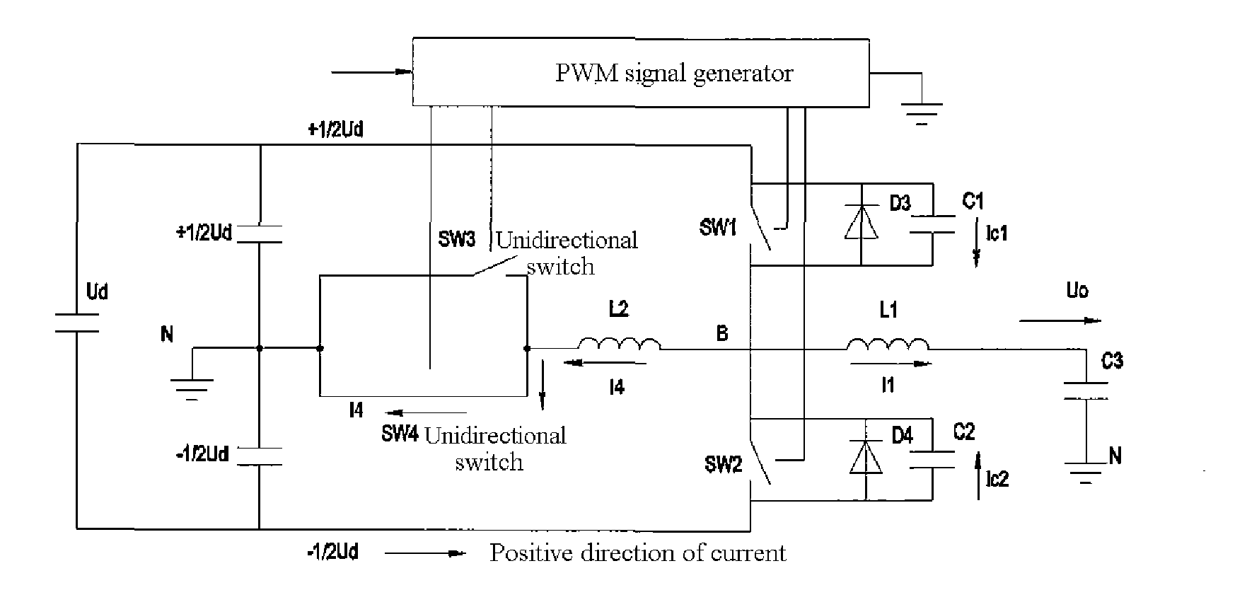
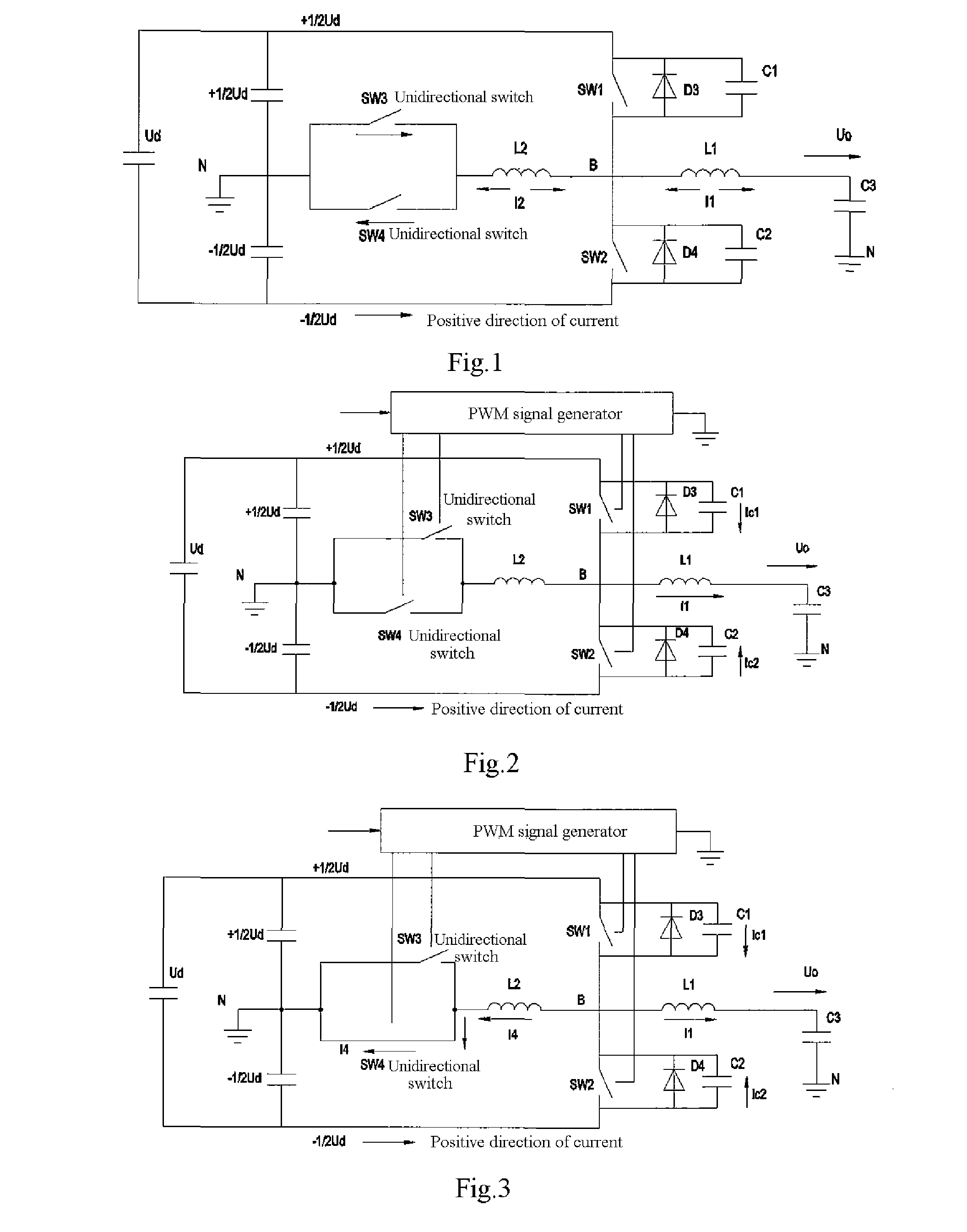
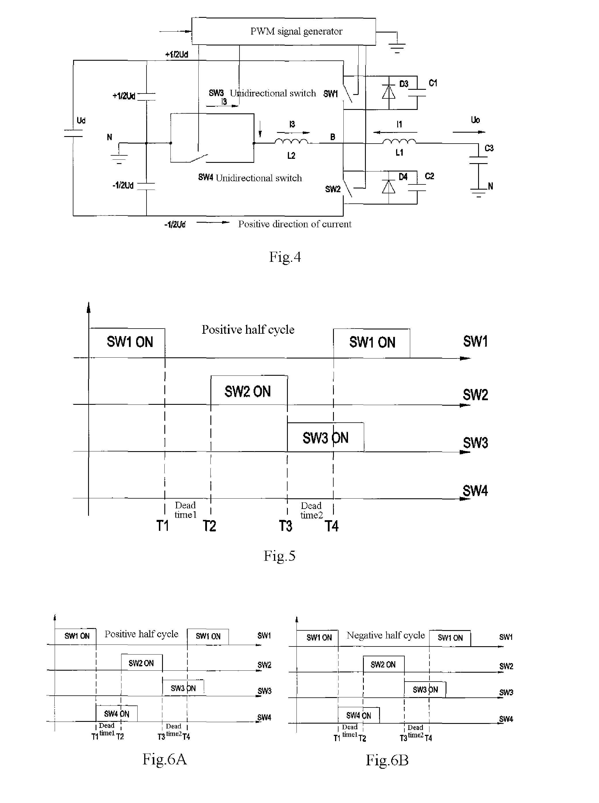
[0035]As illustrated in FIG. 6A, a modified control process in the positive half cycle is as follows: the PWM signal generator controls the forward auxiliary switch device SW4 which would otherwise doe not work to also work so that SW4 is turned on at the time T1 when SW1 is turned off, and turned off after the time T2 when SW2 is turned on. FIG. 3 illustrates a schematic diagram of the operation principle when SW4 is turned on. When the main power filter current I1 is small, particularly around a zero crossing point, the resonant capacitor C1 starts to be charged and the resonant capacitor C2 starts to be discharged at the time T1. Due to the forward auxiliary switch device SW4 being turned on and in the present embodiment only a current in the negative direction passing through the forward auxiliary switch device SW4, a compensation current I4 is generated across a resonant current branch in the opposite direction to the main power filter current I1. At this ti...

second embodiment

THE SECOND EMBODIMENT

[0038]A timing control on the switch devices is performed as in the schematic diagrams of switch logics illustrated in FIG. 7A and FIG. 7B. Specifically, further to the timing control steps of the existing ARCP soft switch circuit: in the positive half cycle, SW4 is turned on at the time T1 when SW1 is turned off, and turned off at the time T2 when SW2 is turned on, i.e., in the turn-on state in the first dead time [T1˜T2]; and in the negative half cycle, SW3 is turned on at the time T3 when SW2 is turned off, and turned off at the time T4 when SW1 is turned on, i.e., in the turn-on state in the second dead time [T3˜T4]. Similarly to the first embodiment, a charging and discharging process of the resonant capacitors C1 and C2 can be accomplished respectively in the first and second dead time.

third embodiment

THE THIRD EMBODIMENT

[0039]A timing control on the switch devices is performed as in the schematic diagrams of switch logics illustrated in FIG. 8A and FIG. 8B. Further to the timing control steps of the existing ARCP soft switch circuit: in the positive half cycle, SW4 is turned on at the time T1 when SW1 is turned off, and turned off before the time T2 when SW2 is turned on; and in the negative half cycle, SW3 is turned on at the time T3 when SW2 is turned off, and turned off before the time T4 when SW1 is turned on. Similarly to the first embodiment, a charging and discharging process of the resonant capacitors C1 and C2 can be accomplished respectively in the first and second dead time.


PUM


Abstract

The present invention relates to a control method for a soft switch circuit in a switch power supply, which controls first and second main power switch devices to be turned on and turned off constantly to generate an alternating main power filter current, and controls forward and backward auxiliary switch devices to be turned on and turned off to generate an intermittent alternating resonant current across a resonant branch in the same direction as the main power filter current to thereby achieve zero-voltage turn-on of the first and second main power switch devices; and further controls the forward and backward auxiliary switch devices to be turned on and turned off to generate compensation currents across the resonant branch in the opposite direction to the alternating main power filter current in at least a period of time during resting of the resonant current to thereby accomplish a charging and discharging process of resonant capacitors in a dead time. Thus, a freewheeling diode can be turned on normally, so that it is possible to avoid a damage to the devices due to an impact current and a spark voltage resulting at zero crossing of the current in the soft switch circuit.

Description

FIELD OF THE INVENTION [0001]The present invention relates to a switch power supply, and in particular to a control method for a soft switch circuit in a switch power supply.BACKGROUND OF THE INVENTION [0002]Switch power supplies are currently in the trend of developing towards high frequency and miniaturization, high power density, high efficiency and low cost. Since semiconductor devices function as hard switches and suffer from a great loss, traditional switch circuits fail to improve their own efficiencies and thus become less competitive in the market due to their bulkiness. In view of limitations of the development in the industry of semiconductor devices, the cost, etc., a soft switch circuit topology has become an option for a majority of switch power supply manufacturers to improve competitiveness of products. There are numerous researches and patents on soft switch circuits, and one of them is a soft switch circuit of Auxiliary Resonant Commutated Pole (ARCP) in the form o...

Claims


Application Information

Patent Timeline
IPC IPC(8): H03K17/687H02B99/00
CPCH02M3/158H02M7/537Y02B70/1425Y02B70/1441Y10T307/76Y02B70/10
Inventor ZHANG, CHUNTAOZHANG, XIAOFEIXIAO, XUELI
Owner VERTIV CORP
Why Eureka
Try Eureka