
Delivery system for endoluminal devices

a technology of endoluminal devices and delivery systems, which is applied in the field of intraluminal medical devices introduction or delivery systems, can solve the problems of inability to place embolic protection devices, inability to accurately guide, and difficulty in reaching and crossing narrowed vessels, etc., and achieves the effects of convenient and fast delivery, convenient use, and superior torque control and flexibility

Inactive Publication Date: 2010-12-16
COOK INC
View PDF3 Cites 2 Cited by
  • Summary
  • Abstract
  • Description
  • Claims
  • Application Information

AI Technical Summary

Benefits of technology

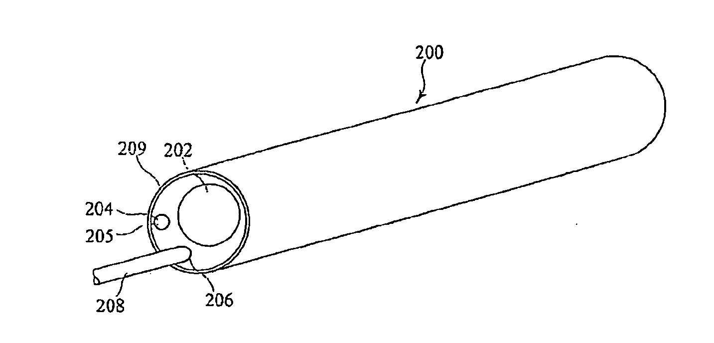
[0011]According to another aspect of the present invention there is provided an introducer for delivering an implant or other medical device within a patient, comprising a delivery catheter including a distal end and a proximal end, the catheter including a delivery lumen for receiving an implant or medical device for delivery and an actuator lumen; an elongate actuator wire located within the actuator lumen at a position offset from a centre axis of the delivery catheter and fixed at one of at or proximate the distal end of the delivery catheter and extending beyond the proximal end of the delivery catheter; the elongate actuator element being able to be pulled in a proximal direction from the proximal end of the delivery catheter so as to cause deflection of the delivery catheter.
[0015]The tip deflecting mechanism allows for proper angling of accessory devices in complex anatomy. Furthermore, the preferred embodiments preferably have a short loading length for the accessory devices, making it easy to remove once the accessory device is in place.

Problems solved by technology

In certain critical arteries, such as carotid arteries, the embolic particles may become trapped in small-diameter blood vessels of the brain and may cause a stroke.
The narrowed vessel may be hard to reach and cross due to its location.
This may be due to an almost total occlusion or complicated branch point where the desired vessel is set at a steep angle to the current path the guidewire or EPD is travelling.
In fact, in about 20-30% of carotid stenting situations, the anatomy of the vessel may be too tortuous to permit placement of the embolic protection device in the above-described manner using existing delivery systems.
A tortuous vessel may contain severe bends, kinks or coils that can inhibit delivery of the embolic protection device.

Method used


Image

  • Delivery system for endoluminal devices
  • Delivery system for endoluminal devices
  • Delivery system for endoluminal devices

Examples


Embodiment Construction

[0028]Described herein is an intraluminal delivery system 5 that may be suitable for directing and delivering an embolic protection device 10 to a site distal of a stenosis in a tortuous vessel. The delivery system 5 may advantageously allow carotid stenting procedures to be carried out under a wider range of circumstances.

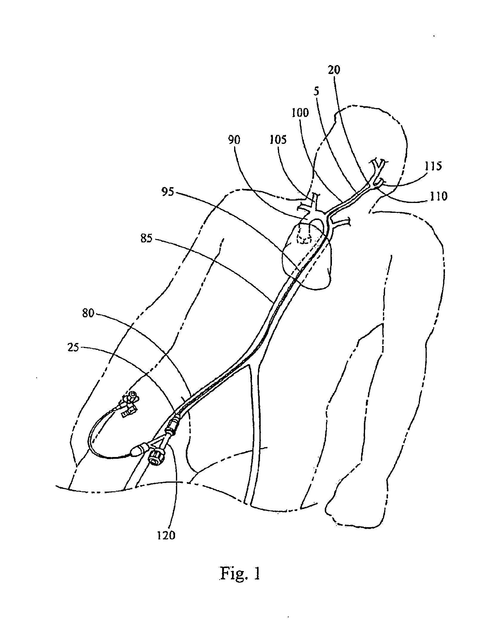
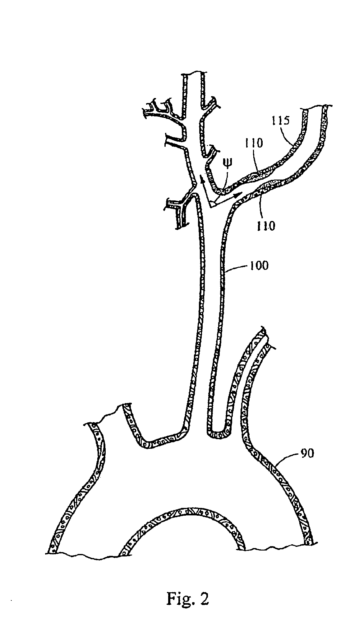
[0029]For example, the intraluminal delivery system 5 may be used to deliver an embolic protection device 10 to a treatment site (e.g., a stenosed region) in a tortuous carotid artery. Typically, to access a carotid artery, a percutaneous incision is made in the femoral artery 80 and an intraluminal medical device is advanced through the aorta 85 and the aortic arch 90. This access route is shown schematically in FIG. 1. Branching from the aortic arch 90 are the left common carotid artery 100 and the right common carotid artery 105, which supply blood to the head and neck, as shown in FIG. 2. A stenosed region 110 is shown in the internal carotid artery 115 extend...


PUM


Abstract

An introducer or delivery system for introducing implants or medical devices such as embolic protection devices within a patient allows deployment within vessels having a tortuous anatomy. The delivery system includes an actuator wire within the delivery catheter which enables the delivery catheter to be bent near a distal end thereof upon actuation of the actuator wire.

Description

FIELD OF THE INVENTION[0001]The present invention relates to an introducer or delivery system for intraluminal medical devices, in an example, to a delivery system for embolic protection devices. The taught introducer can also be used for delivering stents, stent grafts, vena cava filters, occlusion devices and other forms of implant, as well as for other procedures such as balloon angioplasty.BACKGROUND OF THE INVENTION[0002]Balloon angioplasty and stenting procedures are widely used in the treatment of stenoses of the coronary arteries as an alternative to invasive bypass surgeries. However, the inflation of a balloon or placement of a stent at the stenosed region can dislodge embolic particles from the lesion that may travel downstream (distal) of the stenosis. In certain critical arteries, such as carotid arteries, the embolic particles may become trapped in small-diameter blood vessels of the brain and may cause a stroke.[0003]To increase the safety of carotid angioplasty and s...

Claims


Application Information

Patent Timeline
Patent Type & Authority Applications(United States)
IPC IPC(8): A61F2/06
CPCA61F2/013A61F2230/0006A61F2/95A61F2/962
Inventor KONTOS, DAPHNE A.
Owner COOK INC
Learn More