Methods of Forming Micromechanical Resonators Having High Density Trench Arrays Therein that Provide Passive Temperature Compensation

Inactive Publication Date: 2010-12-23
GEORGIA TECH RES CORP
View PDF33 Cites 19 Cited by
  • Summary
  • Abstract
  • Description
  • Claims
  • Application Information

AI Technical Summary

Benefits of technology

[0007]Methods of forming micromechanical resonators operable in a bulk acoustic mode include forming a resonator body anchored to a substrate by at least a first anchor. This resonator body may include a semiconductor or other first material having a negative temperature coefficient of elasticity (TCE). A two-dimensional array of spaced-apart trenches are provided in the resonator body. These trenches may be filled with an electrically insulating or oth

Problems solved by technology

Unfortunately, even when efforts to reduce the adverse effects of variations in photolithography, etching and film thickness on resonant frequency are successful, additional changes in resonant frequency may occur in response to changes in operating temperature.
However, because circuit

Method used


Image

  • Methods of Forming Micromechanical Resonators Having High Density Trench Arrays Therein that Provide Passive Temperature Compensation
  • Methods of Forming Micromechanical Resonators Having High Density Trench Arrays Therein that Provide Passive Temperature Compensation
  • Methods of Forming Micromechanical Resonators Having High Density Trench Arrays Therein that Provide Passive Temperature Compensation

Examples


Embodiment Construction

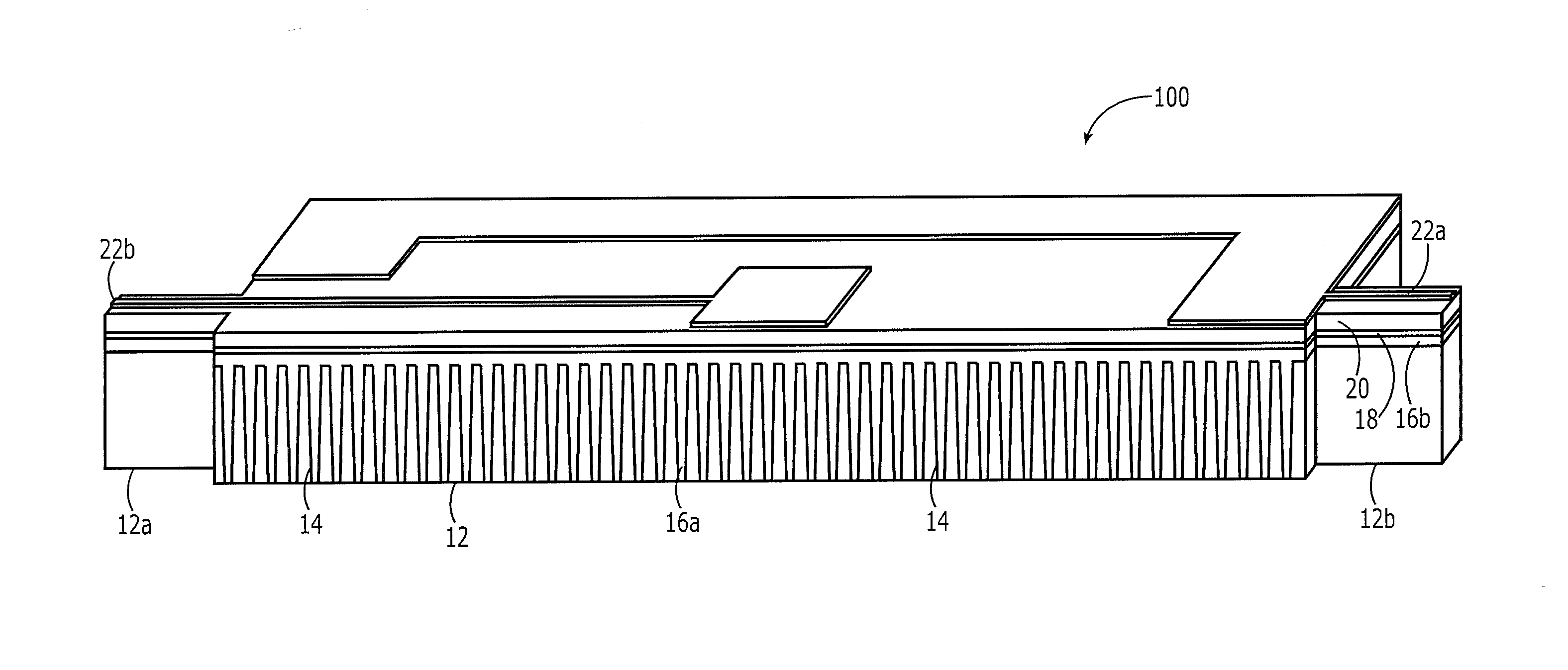
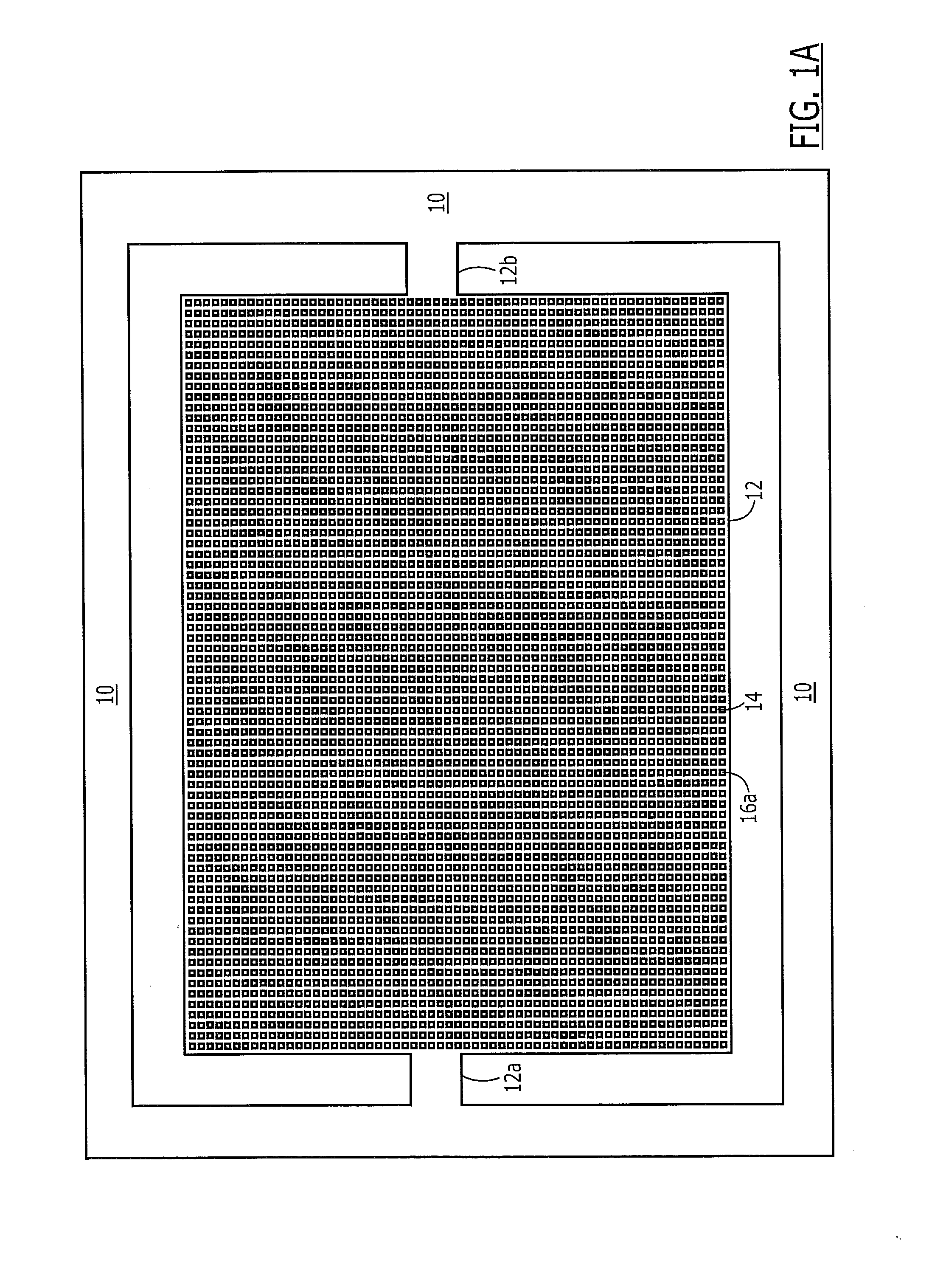
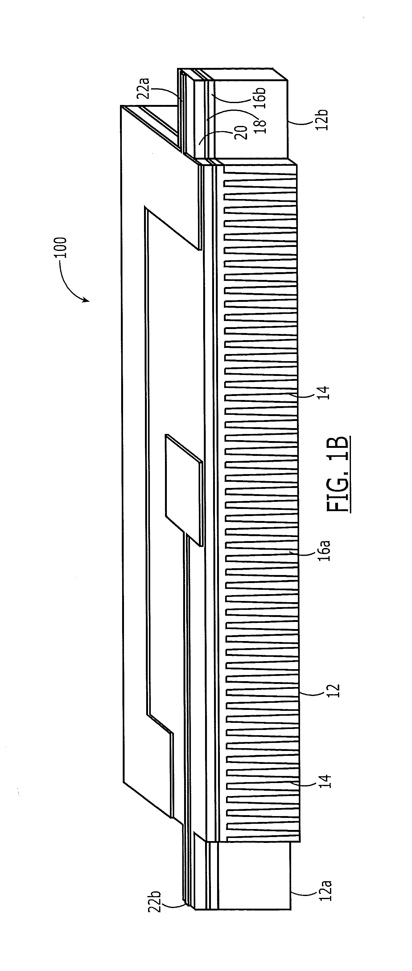
[0017]The present invention now will be described more fully with reference to the accompanying drawings, in which preferred embodiments of the invention are shown. This invention may, however, be embodied in many different forms and should not be construed as being limited to the embodiments set forth herein; rather, these embodiments are provided so that this disclosure will be thorough and complete, and will fully convey the scope of the invention to those skilled in the art. Like reference numerals refer to like elements throughout.

[0018]It will be understood that when an element or layer is referred to as being “on,”“connected to” or “coupled to” another element or layer (and variants thereof), it can be directly on, connected or coupled to the other element or layer or intervening elements or layers may be present. In contrast, when an element is referred to as being “directly on,”“directly connected to” or “directly coupled to” another element or layer (and variants thereof),...


PUM

PropertyMeasurementUnit
Magnetic fieldaaaaaaaaaa
Lengthaaaaaaaaaa

Abstract

A method of forming a micromechanical resonator includes forming a resonator body anchored to a substrate by at least a first anchor. This resonator body may include a semiconductor or other first material having a negative temperature coefficient of elasticity (TCE). A two-dimensional array of spaced-apart trenches are provided in the resonator body. These trenches may be filled with an electrically insulating or other second material having a positive TCE. The array of trenches may extend uniformly across the resonator body, including regions in the body that have relatively high and low mechanical stress during resonance. This two-dimensional array (or network) of trenches can be modeled as a network of mass-spring systems with springs in parallel and/or in series with respect to a direction of a traveling acoustic wave within the resonator body during resonance.

Description

REFERENCE TO PRIORITY APPLICATIONS[0001]This application claims priority to U.S. Provisional Application Ser. Nos. 61 / 218,518, filed Jun. 19, 2009 and 61 / 314,290, filed Feb. 16, 2010, the disclosures of which are hereby incorporated herein by reference.REFERENCE TO RELATED APPLICATIONS[0002]This application is related to U.S. application Ser. No. 12 / 535,284, filed Aug. 4, 2009, the disclosure of which is hereby incorporated herein by reference.FIELD OF THE INVENTION[0003]The present invention relates to integrated circuit devices and methods of forming same and, more particularly, to micromechanical devices and methods of forming same.BACKGROUND OF THE INVENTION[0004]Micro-electromechanical (MEMs) resonators can provide small form factor, ease of integration with conventional semiconductor fabrication techniques and high f·Q products. High frequency and high-Q width-extensional mode silicon bulk acoustic resonators (SiBARs) and film bulk acoustic wave resonators (FBARs) have demonst...

Claims


Application Information

Patent Timeline
IPC IPC(8): H04R31/00
CPCH03H3/0076H03H9/02448Y10T29/49155Y10T29/42Y10T29/49005H03H2009/2442
Inventor AYAZI, FARROKHTABRIZIAN, ROOZBEHCASINOVI, GIORGIO
Owner GEORGIA TECH RES CORP
Why Eureka
Try Eureka