Utility Cutter

a utility cutter and cutting tool technology, applied in the direction of thrusting weapons, white arms/cold weapons, weapons, etc., can solve the problems of high operator injury risk, injury to the user or others, and high chance of operator injury, so as to prevent the blade from being decoupled, the cutting or cutting of near frictionless or low friction materials is safer. , the effect of preventing the blade from falling o

a utility cutter and cutting tool technology, applied in the direction of thrusting weapons, white arms/cold weapons, weapons, etc., can solve the problems of high operator injury risk, injury to the user or others, and high chance of operator injury, so as to prevent the blade from being decoupled, the cutting or cutting of near frictionless or low friction materials is safer. , the effect of preventing the blade from falling o

US20100319200A1Active Publication Date: 2010-12-23ADCO IND TECH

Image

  • Utility Cutter
  • Utility Cutter
  • Utility Cutter

Examples


Embodiment Construction

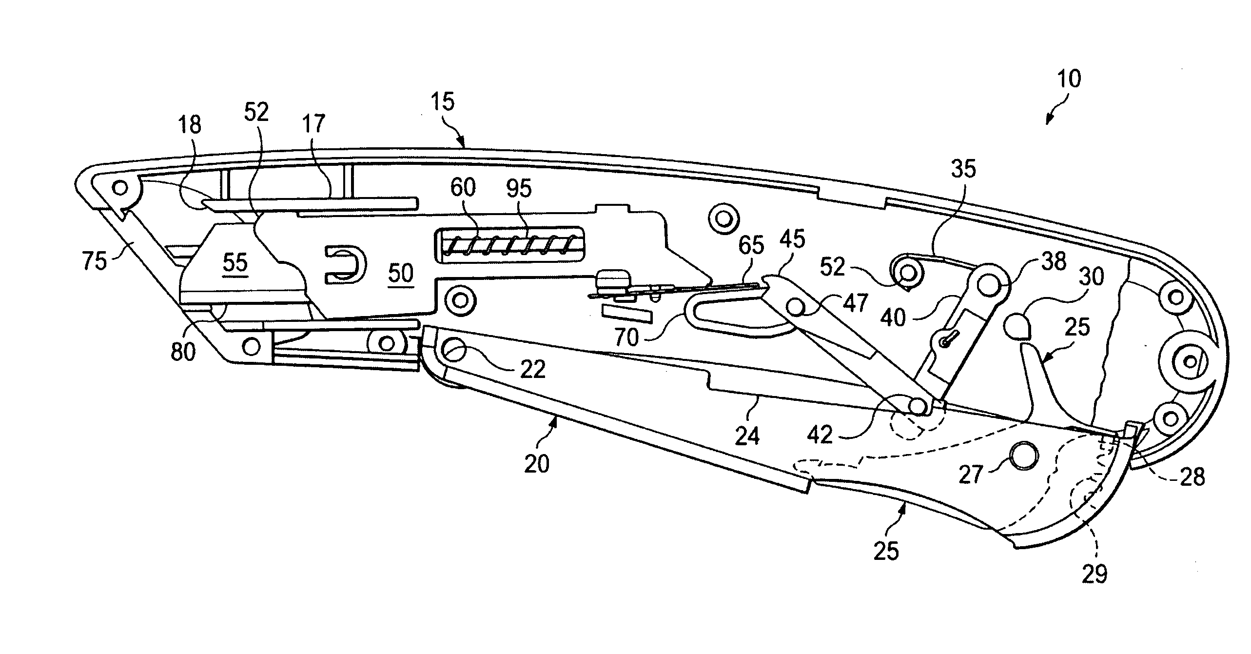
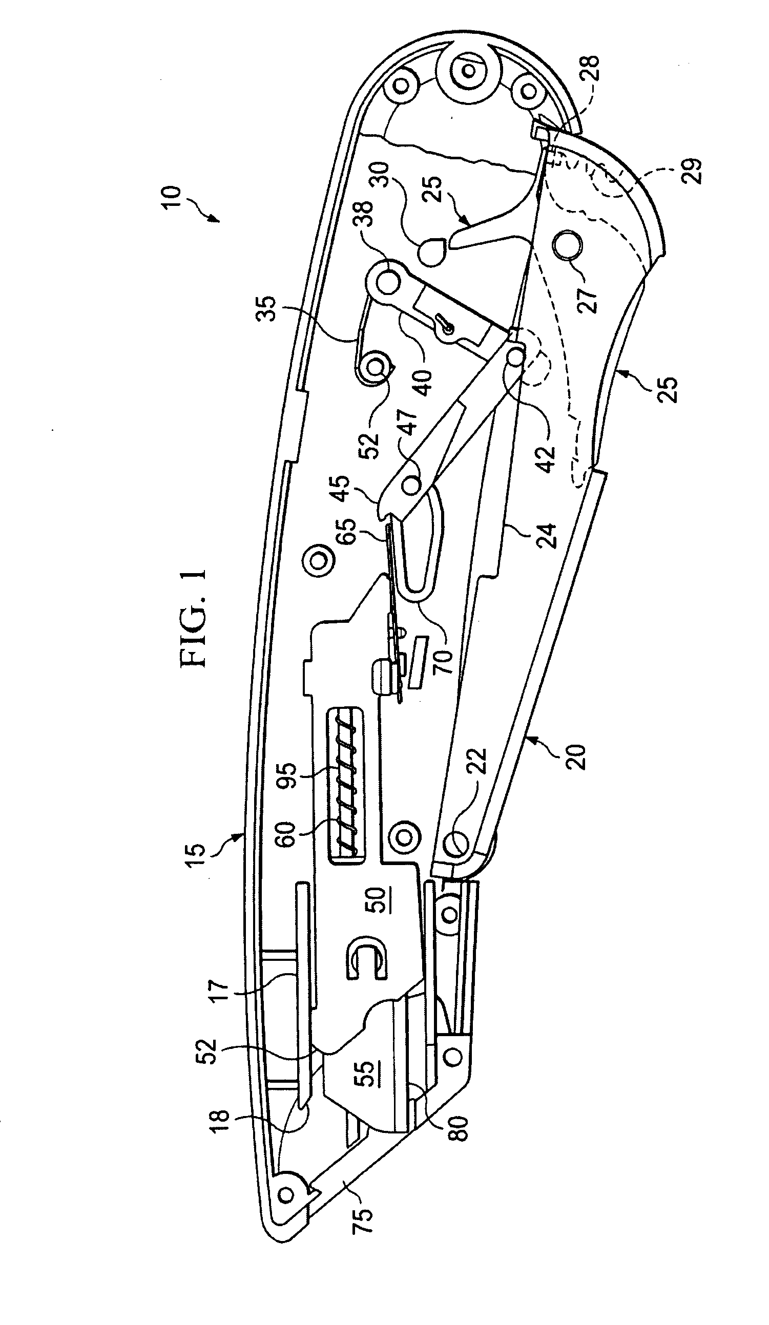
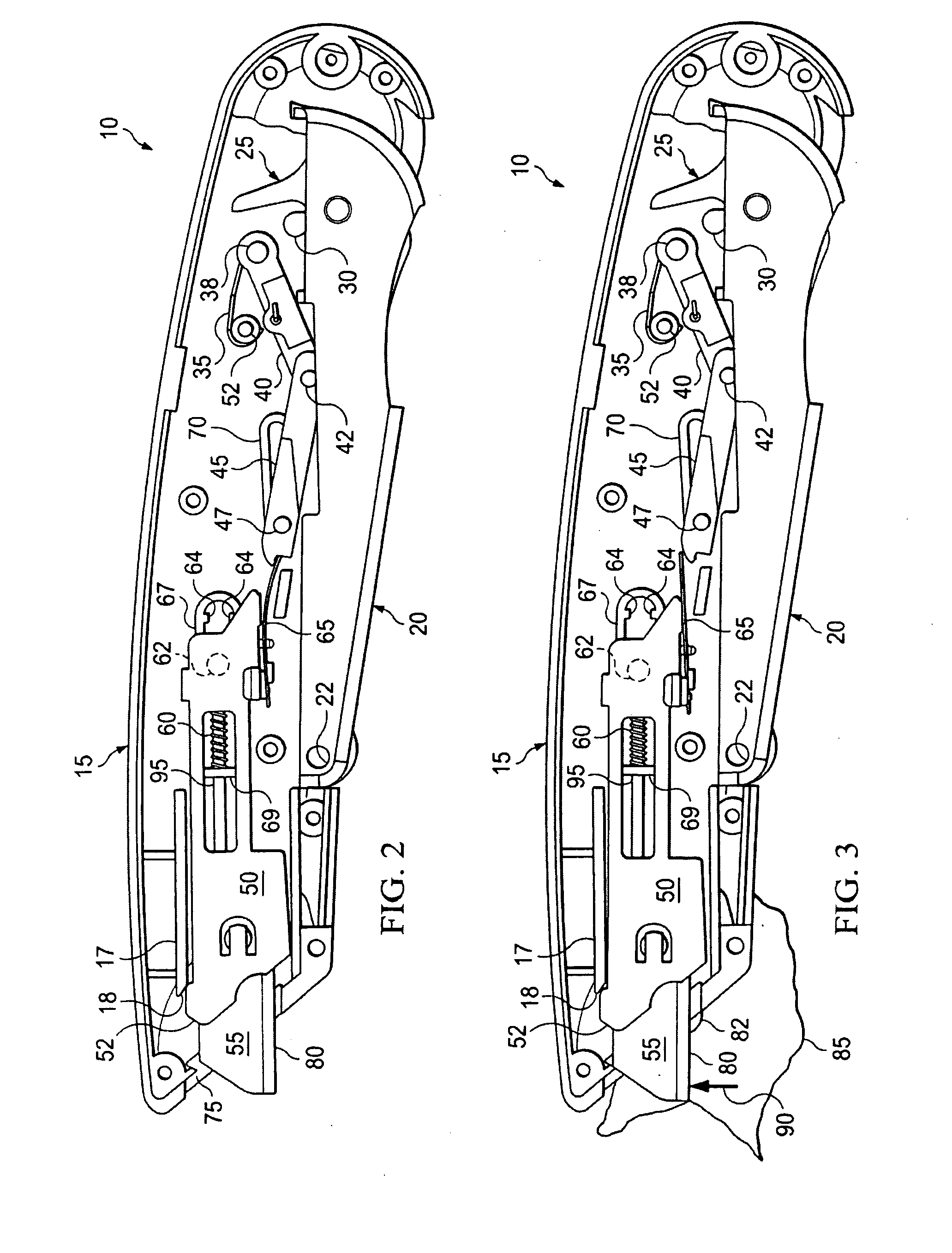
[0025]A utility cutter according to the present disclosure, generally, includes a protective handle or housing operable to enclose a blade shuttle and a blade coupled to the blade shuttle. Upon actuation of the utility cutter by a user by, for example, rotating a blade trigger, the blade shuttle and blade may be extended. At least a portion of the blade is exposed from the housing once the blade shuttle is extended. The user may cut or slice a variety of materials, such as polyfilm, corrugated board, adhesive tape, plastic bags or wrap, or cardboard, with the exposed blade. To ensure or increase the safety of the user, other persons, or valuable property, the exposed blade may automatically retract within the housing when the blade becomes disengaged from the material. For instance, a force directed substantially perpendicular to a cutting edge of the blade may disengage the blade shuttle (or a component attached thereto, such as a leaf spring) from one or more components of a blade...


PUM


Abstract

A knife according to the present disclosure includes a housing and a blade. The blade includes a blade edge adapted to engage a material, and the blade is coupled to a blade shuttle. The blade and blade shuttle are substantially enclosed within the housing when the blade shuttle is in a retracted position, and the blade is extended from the housing when the blade shuttle is in an extended position. The blade shuttle is adapted to be conveyed to the retracted position based on the blade receiving a force directed substantially perpendicular to the blade edge.

Description

TECHNICAL BACKGROUND[0001]This disclosure relates to cutting rigid, semi-rigid, and flexible materials, and more particularly, to cutting rigid, semi-rigid, and flexible materials with a utility cutter including a cutting blade retractable in response to force from one or more directions.BACKGROUND[0002]Utility cutters may be used to cut or slice a variety of materials, such as cardboard, corrugated board of varying thickness, rubber, lightweight plastic, or other packaging material. In order to cut or slice such material, the utility cutter may need to have a sharpened blade. Certain precautions may be used to protect or help protect a user from the sharpened blade. For example, a utility cutter may include guards that extend from the cutter alongside the sharpened blade, such that the guards substantially prevent an accidental injury to the user or other bystander. Further, a utility cutter may include a protective handle that encloses substantially all of a blade during periods o...

Claims


Application Information

Patent Timeline
23 Dec 2010
Publication
US20100319200A1
IPC
B26B3/06
CPC
B26B5/003
Inventors
DAVIS, RAYMOND E.; HAMPTON, CLIFTON GLENN