Structure for radio frequency identification and its manufacturing method

a radio frequency identification and manufacturing method technology, applied in the direction of slot antennas, instruments, antennas, etc., can solve the problems of easy affecting of the electrical properties of the rfid, rfid reader cannot correctly read the data, complex manufacturing methods, etc., to achieve a simple and cheaper method, reduce manufacturing costs, and low power energy consumption

Inactive Publication Date: 2010-12-23
ELKA INT
View PDF7 Cites 20 Cited by
  • Summary
  • Abstract
  • Description
  • Claims
  • Application Information

AI Technical Summary

Benefits of technology

[0015]The improved structure of an RFID of the present invention comprises: a substrate with an entire side of metal conductive material; a slot antenna disposed on the metal side of the substrate; and an identification chip disposed on the substrate and electrically connected to the slot antenna. Subsequently, the RFID is manufactured using a simpler and cheaper method, so that manufacturing costs are significantly reduced, while enjoying the benefits of low power energy consumption, no pollution, recyclability, and an RFID having high antenna gain, strong reflectivity, and high conductivity. Furthermore, the shield effect provided by the entire metal side of the substrate can also reduce the effects of the electrical property of the RFID caused by the target object and the environment, so the RFID is more suitable for metal objects and conductors with moisture.

Problems solved by technology

However, this manufacturing method is complicated and expensive; the conductive emulsion antenna has a very limited area; the shield effect of the surrounding plastic film or paper substrate is poor so that the electrical properties of the RFID are easily affected by metal and moisture in the background environment, and as a consequence the RFID reader cannot correctly read the data.
Furthermore, the application of the prior art RFID has the following problems:
1. High cost: very expensive machinery is required to perform printing for the antennas or etching on the plastic film or paper substrate.
In addition, emulsion is a high cost, perishable material, while high cost pollution treatment processes for etching also increase the manufacturing costs of the antenna of the radio frequency tag.
2. Low yield: the emulsion printing materials for emulsion and sputtering are in particulate form, which has poor conductivity in comparison to continuous conductive metal materials, and the finished antenna tends to break and fail easily.
Etching may cause poor and discontinuous conductivity of the antenna due to under-exposure or over-exposure.
3. Low accuracy of electrical properties: due to uneven thickness of the emulsion and uneven etching, the electrical conductivity and magnetic induction of the antenna impedance may be unevenly distributed which causes frequency drift and impedance mismatching of the antenna so that accuracy is hard to control and the failure rate is increased.
4. Low endurance: the printing emulsion frequently evaporates, while corrosion of etched wires, all make the radio frequency tag hard to stock with a short operational lifetime.
After all of these repeated procedures, the customization costs are very high and the goal of single material preparation and single stocks cannot be achieved.

Method used


Image

  • Structure for radio frequency identification and its manufacturing method
  • Structure for radio frequency identification and its manufacturing method
  • Structure for radio frequency identification and its manufacturing method

Examples


Embodiment Construction

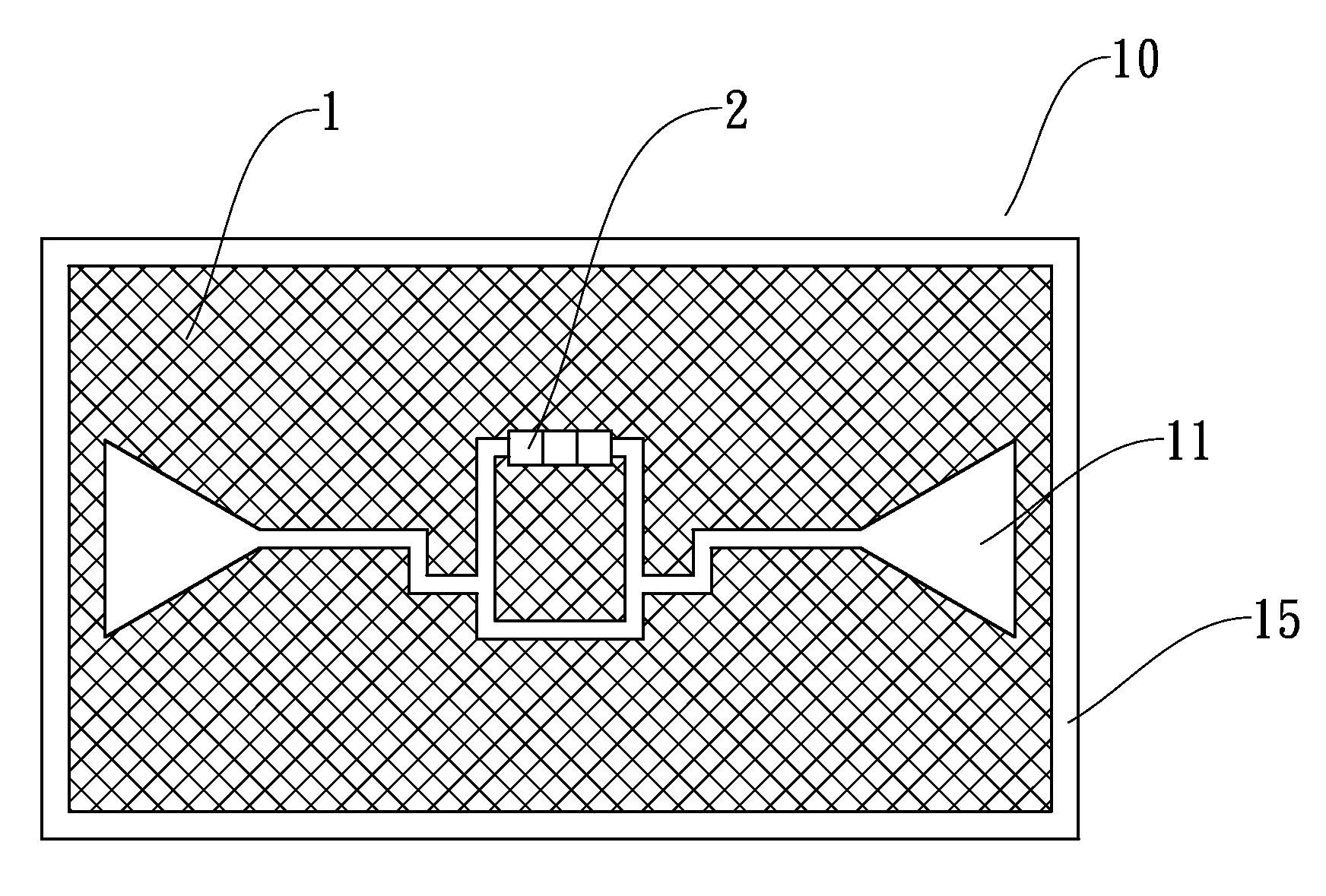
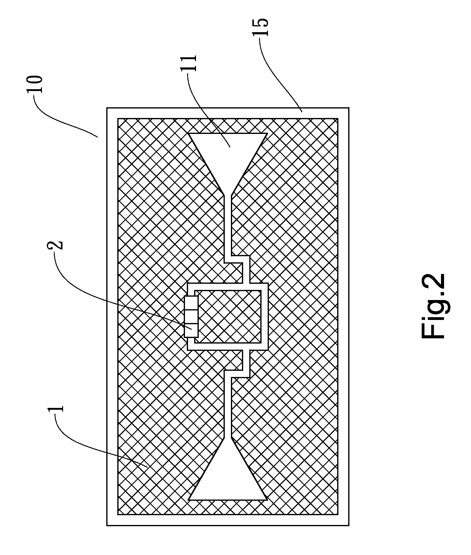
[0029]As shown in FIGS. 2˜3, an RFID tag 10 of the present invention comprises:

[0030]a substrate 1 with an entire side of metal conductive material;

[0031]a slot antenna 11 disposed on the metal side of the substrate 1; and

[0032]an identification chip 2 disposed on the substrate and electrically connected to the slot antenna.

[0033]The finished tag 10 can be laminated with a lamination frame 15 and be provided with different configurations; for example, the slot antenna 11 of the substrate 1 may have two symmetrical (as shown in FIG. 2) or two asymmetrical (as shown in FIG. 3) closed slots, or a two-sided opened slot (as shown in FIG. 4), or a single closed slot and one opened slot (as shown in FIG. 5).

[0034]Since the RFID of the present invention is very different from the prior art structure, a more simplified and efficient manufacturing method is performed. As shown in FIGS. 6˜7, the manufacturing method comprises:

[0035](A) selecting a substrate 1 with an entire side having continu...


PUM


Abstract

A improved structure RFID includes: a substrate with an entire side of a metal conductive material; a slot antenna disposed on the metal side of the substrate; and an identification chip disposed on the substrate and electrically connected to the slot antenna. The RFID is manufactured using a simpler and cheaper method, so manufacturing costs are significantly reduced while providing low energy consumption, pollution-free, recyclability, and the RFID has high antenna gain, strong reflectivity, and high conductivity. Shield effects provided by the whole metal side of the substrate can also reduce effects to the electrical properties of the RFID caused by the target object and the environment, so the RFID is more suitable for metal objects and conductors with moisture.

Description

BACKGROUND OF THE INVENTION[0001]1. Field of the Invention[0002]The present invention relates to an improved structure for radio frequency identification and its manufacturing method, and, more particularly, to an RFID having a slot antenna on its conductive substrate which can provide high antenna gain, strong reflectivity, and high conductivity.[0003]2. Description of the Related Art[0004]The RFID (radio frequency identification), also called an electronic tag, is a communication technology between an identification system and a specific target via radio signals without mechanical or optical contacts.[0005]Currently, passive RFID tags are more popular, because they are cheaper and require no power. In practice, an identification chip in an RFID tag is driven by the electromagnetic wave from an RFID reader; when the tag receives a sufficient signal it sends data to the reader. This data includes an ID number (globally unique ID) and information pre-stored in an EEPROM on the tag.[0...

Claims


Application Information

Patent Timeline
Patent Type & Authority Applications(United States)
IPC IPC(8): G06K19/06
CPCG06K19/07786H01Q1/2225H01Q13/16H01Q13/10H01Q13/085
Inventor FU, I-JU
Owner ELKA INT
Why Eureka
Try Eureka