Imaging lens

a technology of imaging lens and image surface, applied in the field of imaging lens, can solve the problems of difficult to achieve both miniaturization and satisfactory aberration correction, and the focal length of the lens system is relatively long, so as to achieve good image-forming performance, reduce the thickness of the imaging lens, and maintain the flat image surface

Active Publication Date: 2010-12-23
TOKYO VISIONARY OPTICS CO LTD
View PDF6 Cites 4 Cited by
  • Summary
  • Abstract
  • Description
  • Claims
  • Application Information

AI Technical Summary

Benefits of technology

[0009]When the conditional expression (1) is satisfied, it is possible to reduce a length (a thickness) of the imaging lens along an optical axis thereof.
[0010]According to the invention, the first lens is formed in the shape so that both the curvature radius of the surface thereof on the object side and the curvature radius of the surface thereof on the image side are positive, i.e., the shape to be a meniscus lens near the optical axis. Further, the second lens is formed in the shape so that the curvature radius of the surface thereof on the object side is negative and the curvature radius of the surface thereof on the image side is positive, i.e., the shape to be a biconcave lens near the optical axis. With the configuration, refractive power of the second lens becomes stronger than that of the first lens. Accordingly, it is possible to properly reduce a size of the imaging lens, especially the thickness of the imaging lens.
[0016]When the conditional expression (4) is satisfied, it is possible to restrain an incident angle of a light beam emitted from the imaging lens to an imaging element within a certain range, and also restrain astigmatism and the field curvature within optimal ranges. As well known, in order for an imaging element to receive a light beam, an incident angle of the light beam needs to be below a maximum incident angle according to a structure of the imaging element. When the light beam outside the range of the maximum incident angle enters the imaging element, a resultant image tends to have a dark periphery due to a shading phenomenon. Accordingly, it is necessary to restrain the incident angle of the light beam emitted from the imaging lens to the imaging element within a certain range.
[0019]When the conditional expression (5) is satisfied, it is possible to maintain flatness of the image surface while reducing the thickness of the imaging lens and obtaining good image-forming performance. When the surface of the third lens on the object side has the curvature radius within a range represented with the conditional expression (5), the position of the principal point of the whole lens system tends to move toward the object side. Further, it is possible to reduce the thickness of the imaging lens in relative to the focal length of the whole lens system, while maintaining the flatness of the imaging surface, thereby making it possible to obtain good imaging performance.
[0020]According to the imaging lens of the invention, the image surface is corrected at the first lens. Accordingly, it is possible to both reduce the size of the imaging lens and correct the aberration properly, thereby making it possible to provide the imaging lens with the small size capable of correcting aberrations properly.

Problems solved by technology

However, the lens system has a relatively long focal length.
Accordingly, it is difficult to reduce a distance of an optical axis from a surface of the first lens on the object side to an image plane.
Therefore, it is difficult to achieve both miniaturization and satisfactory aberration correction.

Method used


Image

  • Imaging lens
  • Imaging lens
  • Imaging lens

Examples


Embodiment Construction

[0036]Hereunder, referring to the accompanying drawings, embodiments of the present invention will be described.

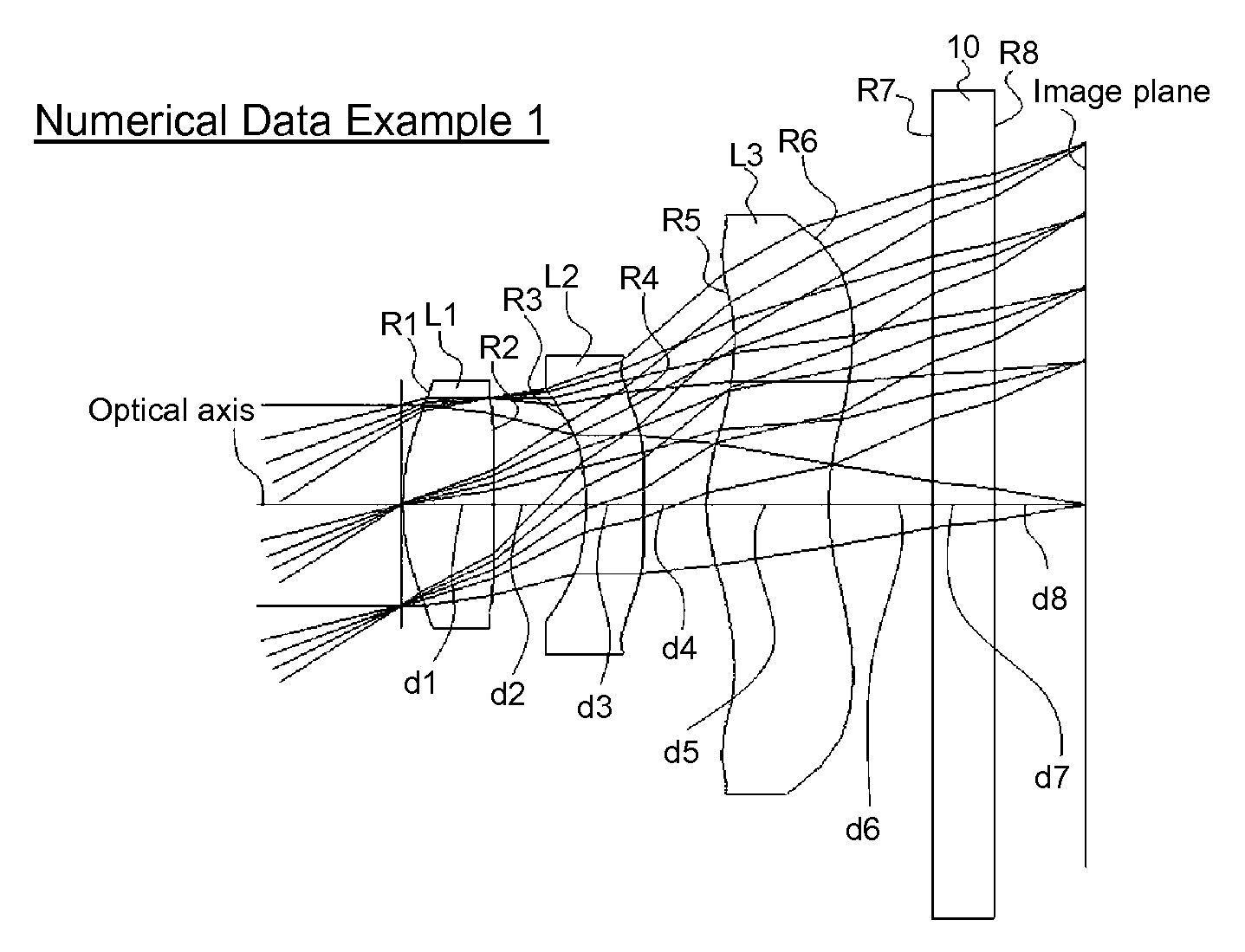
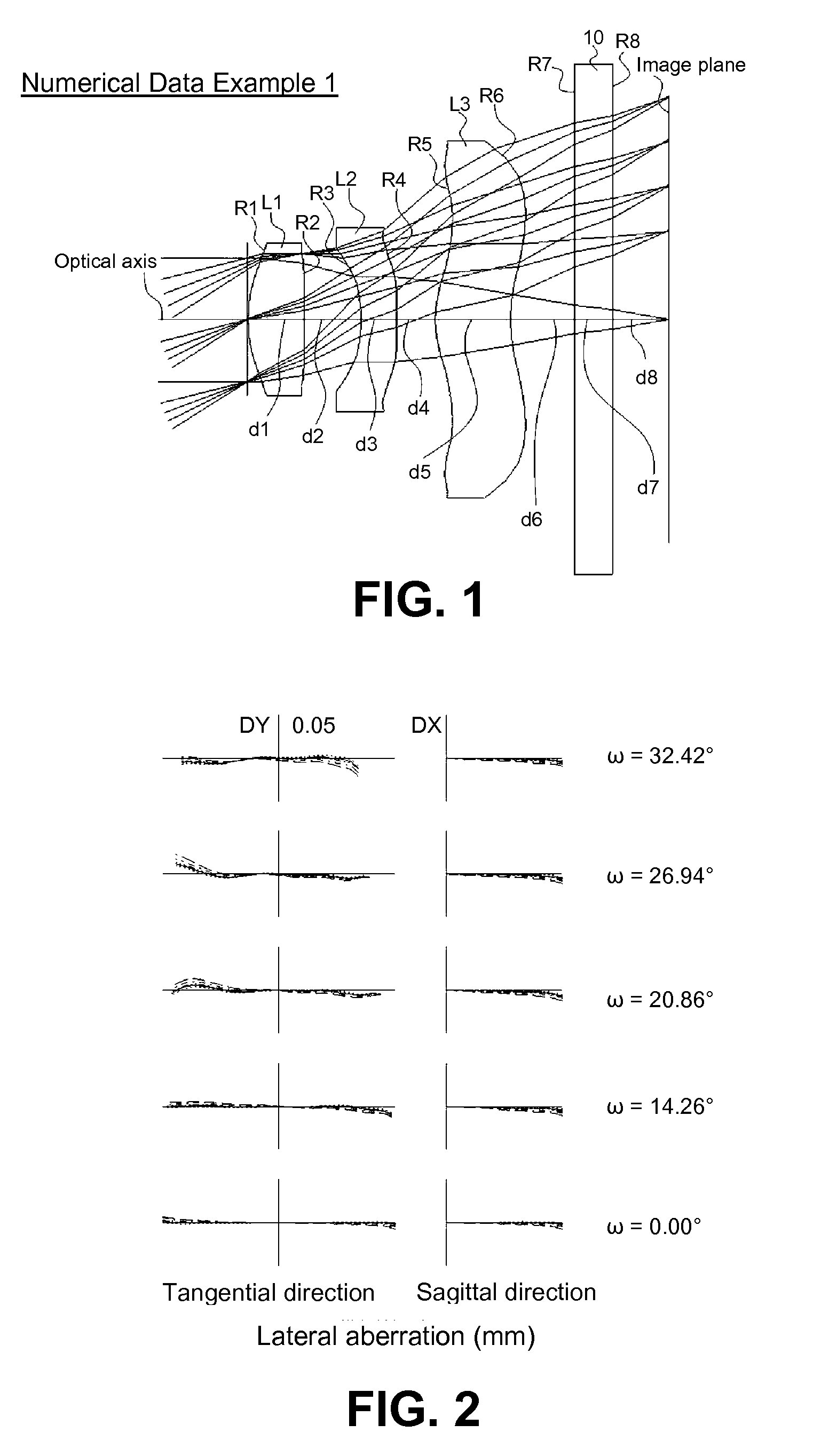
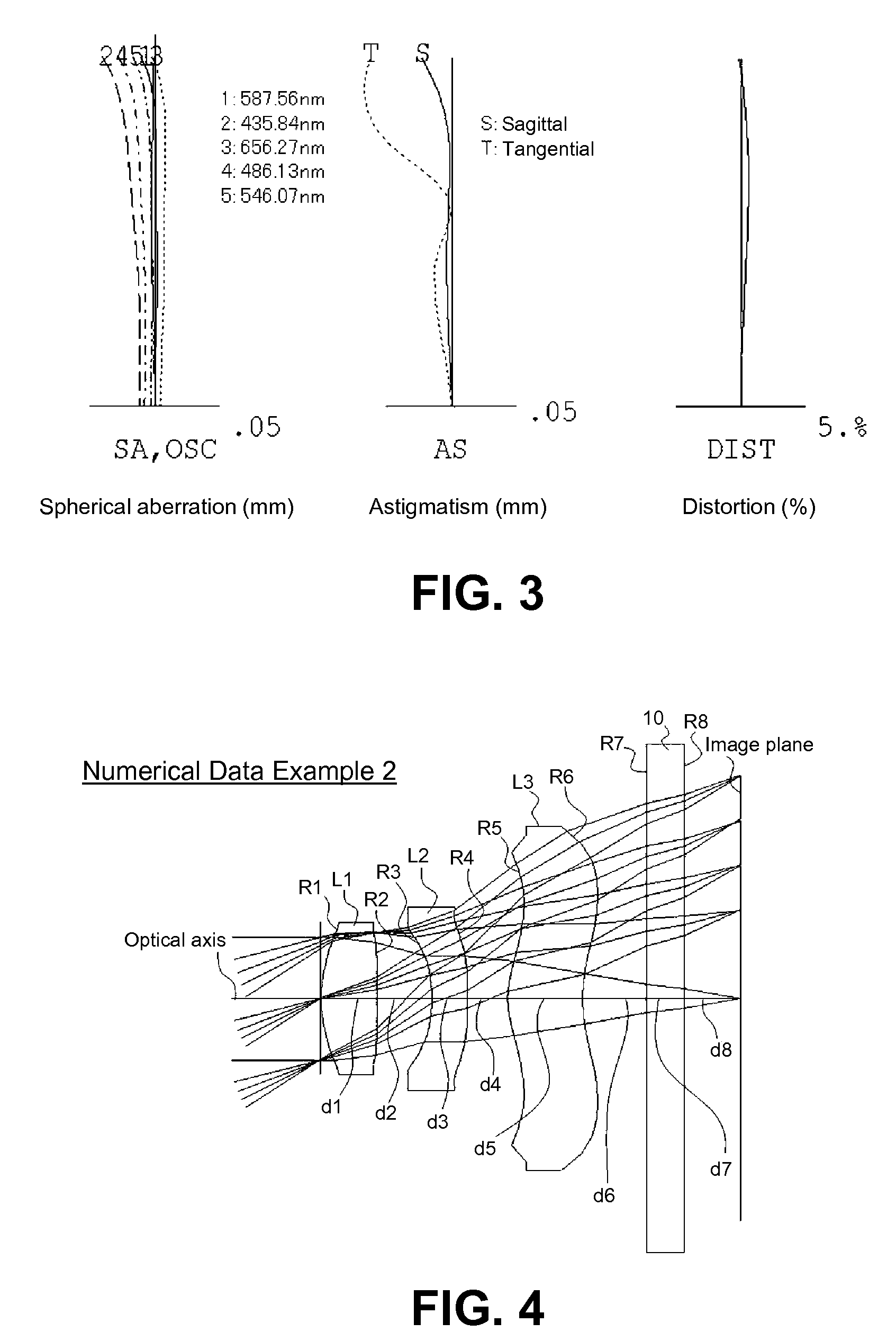
[0037]FIGS. 1, 4, 7, 10, and 13 are schematic sectional views showing image lenses in Numerical Data Examples 1 to 5 according to the embodiment, respectively. Since a basic lens configuration is the same among the Numerical Data Examples 1 to 5, the lens configuration of the embodiments will be described with reference to the lens sectional view of Numerical Data Example 1.

[0038]As shown in FIG. 1, the imaging lens of the embodiment has a first lens L1 having positive refractive power; a second lens L2 having negative refractive power; and a third lens L3 having positive refractive power, which are arranged in this order from an object side to an image side of the imaging lens. A cover glass 10 is provided between the third lens L3 and an image plane of an imaging element. It is noted that the cover glass 10 may be optionally omitted.

[0039]The first lens L1 has an aspheri...


PUM


Abstract

An imaging lens includes a first lens L1 having positive curvature radii on both an object side and an image side, a second lens L2 having a concave shape on both sides, and a third lens L3 having positive curvature radii on both the object side and the image side. The first to third lenses L1 to L3 are arranged in this order from the object side toward the image side. When the first lens L1 has a focal length f1 and the second lens L2 has a focal length f2, the imaging lens is configured such that a relationship f1>|f2| is satisfied.

Description

CROSS-REFERENCE TO RELATED APPLICATIONS[0001]This is a continuation application of a prior PCT application No. PCT JP 2010 / 56540, filed Apr. 12, 2010, pending.BACKGROUND OF THE INVENTION AND RELATED ART STATEMENT[0002]The present invention relates to an imaging lens for forming an image on an imaging element such as a CCD sensor and a CMOS sensor. In particular, the present invention relates to an imaging lens suitable for mounting in a relatively small camera such as a cellular phone, a digital still camera, a portable information terminal, a security camera, an onboard camera, and a network camera.[0003]An imaging lens to be mounted in a small camera has been required to have a high resolution lens configuration suitable for a recently developed imaging element with a high resolution, as well as to use a fewer number of lenses. Conventionally, various lens configurations have been proposed. Among the various lens configurations, a configuration formed of three lenses has been suit...

Claims


Application Information

Patent Timeline
Patent Type & Authority Applications(United States)
IPC IPC(8): G02B9/16
CPCG02B9/16G02B13/18G02B13/0035
Inventor KUBOTA, YOJIKURIHARA, ICHIRO
Owner TOKYO VISIONARY OPTICS CO LTD
Why Eureka
Try Eureka