Eureka AIR delivers breakthrough ideas for toughest innovation challenges, trusted by R&D personnel around the world.

Process for making rare earth containing glass

a rare earth and glass technology, applied in glass rolling apparatus, glass tempering apparatus, natural mineral layered products, etc., can solve the problems of low glass optical efficiency, phase separation problems, concentration quenching, etc., and achieve the effect of reducing concentration quenching and low solubility

Inactive Publication Date: 2010-12-23
SEKISUI CHEM CO LTD +1
View PDF16 Cites 5 Cited by
  • Summary
  • Abstract
  • Description
  • Claims
  • Application Information

AI Technical Summary

Benefits of technology

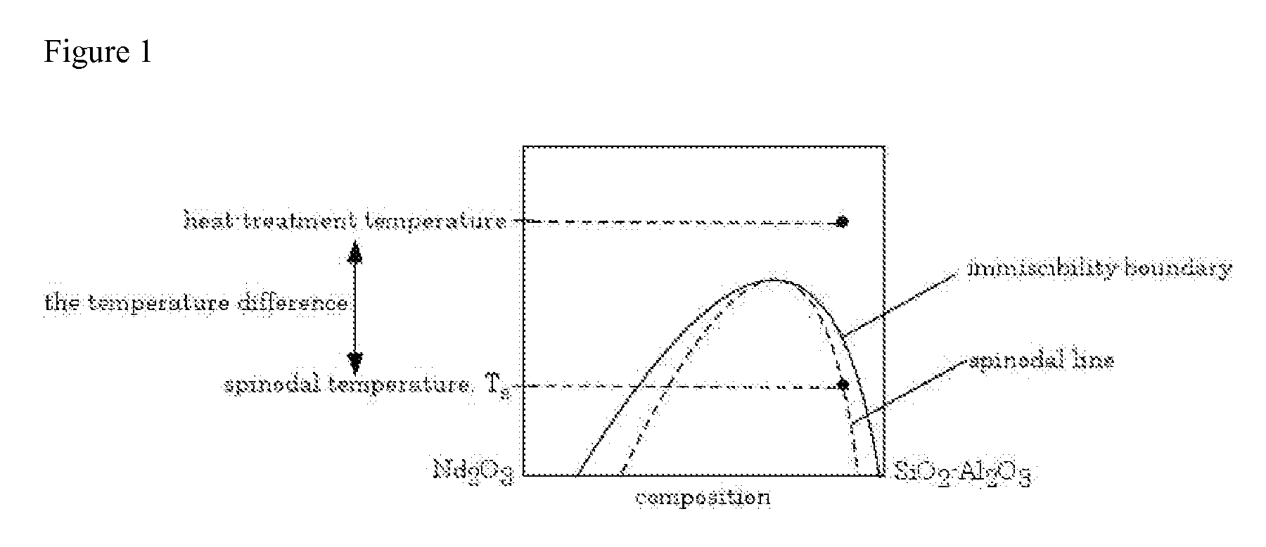
[0008]The problems associated with rare earth glasses such as concentration quenching, low solubility of rare earth oxides and inhomogeneous distributions of the glass components are overcome by the invention. The invention provides a process for preparing rare earth containing SiO2—RExOy—Al2O3 glasses, where RE is a rare earth element and RExOy refers to a rare earth oxide. The subscripts x and y refer to the stoichiometric ratio of rare earth element to oxygen respectively. Most rare earth oxides that are useful in the invention have the stoichiometric ratio RE2O3. The process of the invention includes a step of treating the glass at a temperature higher than the spinodal temperature. The glass, or glasses, prepared by this method are homogeneous, clear, and have reduced concentration quenching.

Problems solved by technology

Existing rare earth doped glasses have encountered some problems due to the low solubility of rare earth ions in SiO2 causing concentration quenching which lowers the optical efficiency of the glass.
At higher percentages of rare earth ions, problems with phase separation are encountered due to the low solubility of rare earth ions in SiO2.
Concentration quenching is another problem associated with rare earth doped SiO2 glasses.
However, these glasses still suffer concentration quenching when the concentration of rare earth ions reaches useful levels.
For example, a problem with the prior art SiO2 glass doped with rare earth elements is that concentration quenching generally becomes significant when the amount of rare earth oxide exceeds 1 mol %.
The problems associated with rare earth glasses such as concentration quenching and low solubility of the rare earths leading to inhomogeneous distributions have limited the usefulness of these glasses.

Method used


Image

  • Process for making rare earth containing glass
  • Process for making rare earth containing glass
  • Process for making rare earth containing glass

Examples


example 1

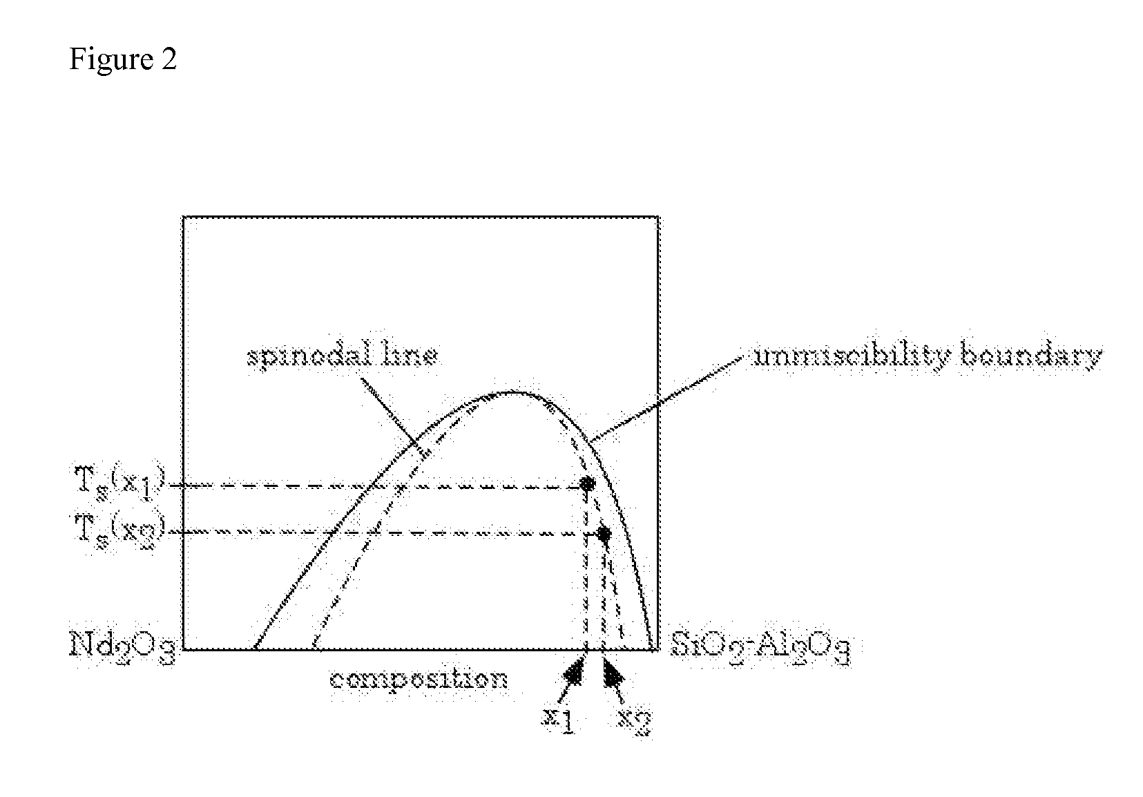
Estimating the Spinodal Lines from the Critical Compositions at 1750° C. and 1600° C. for SiO2—Nd2O3—Al2O3 Glass

[0087]A SiO2—Nd2O3—Al2O3 glass was prepared, in accordance with the process of the invention, by melting. Composition ranges of the glasses were Nd2O3 2.5-40 mol %, Al2O3 0-15 mol % with the balance being SiO2. Batch materials used in glass melting were sol-gel-derived high purity silica powder from Nippon Kasei Chemical Co., Ltd. (MKC® silica PS400L), Nd2O3 powder from Sigma-Aldrich (99.9% purity) and reagent-grade Al2O3 powder from Fisher Scientific. The batch was mixed using an alumina mortar and pestle. Approximately 50 mg of the mixture was put in a 90% Pt-10% Rh boat (ca. 10 mm×10 mm×5 mm) and melted for 1 h at 1750° C. in air. The melted glass was quenched by putting it into water together with the boat. Similar glasses were heat-treated also at 1600° C. before water quenching. To prepare these samples, the glass was melted at 1750° C. for 1 h and then cooled down t...

example 2

Relation of the Immiscibility Boundary to the Volume Fraction

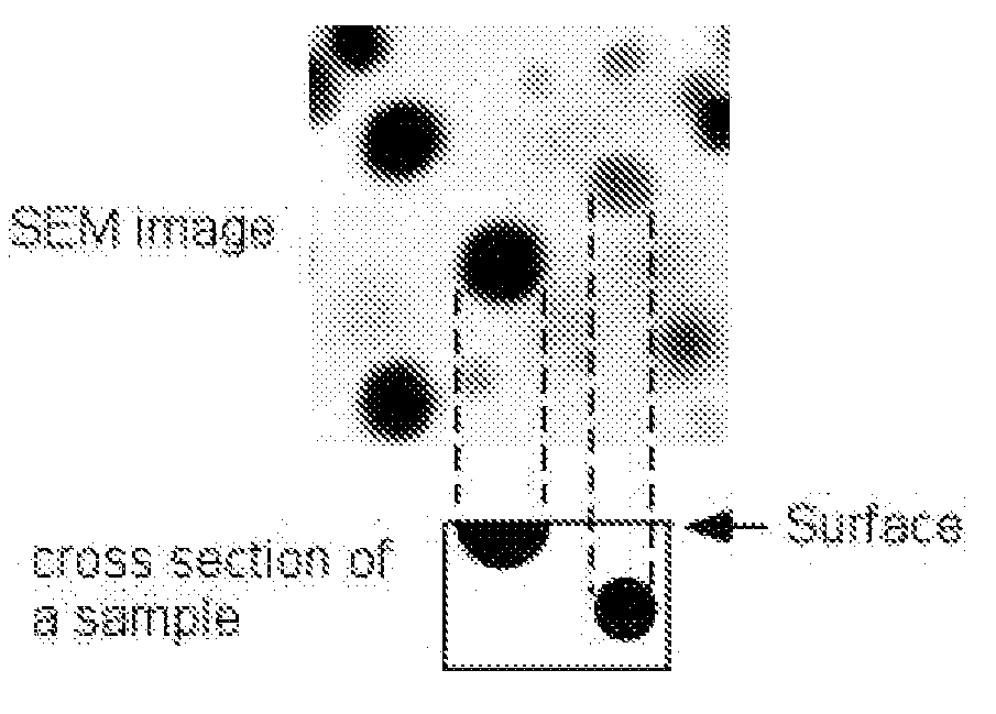
[0092]In order to relate the immiscibility boundary to the volume fraction evaluated, the immiscibility boundary has to be expressed in vol %. This was achieved by first converting mol % to wt % and then to vol %. FIG. 8 shows the immiscibility boundary in wt % which was obtained from the immiscibility boundary in mol % shown in FIG. 7 using the formula weight of each oxide. FIG. 9 shows the immiscibility boundary in vol % which was obtained using the density of each oxide. For SiO2, the density of SiO2 glass, 2.20 g / cm3, was used. For the densities of Nd2O3 and Al2O3, the values of Nd2O3 and Al2O3 at room temperature, 7.24 g / cm3 and 3.99 g / cm3, respectively, were used.

[0093]The volume fractions of separated phases of selected glass samples are shown in Table B. The area fractions in the SEM images are equivalent to the volume fractions of the separated two phases in the sample. Here, as explained earlier in connection wit...

example 3

Phase Diagram at 1750° C.: SiO2—Er2O3—Al2O3 Glass

[0098]SiO2—Er2O3—Al2O3 glasses were prepared by melting. Composition ranges of the glasses were Nd2O3 7.5-26.25 mol %, Al2O3 5-15 mol % with the balance SiO2. Batch materials used in glass melting were sol-gel-derived high purity silica powder from Nippon Kasei Chemical Co., Ltd. (MKC® silica PS400L), Er2O3 powder from Sigma-Aldrich (99.99% purity) and reagent-grade Al2O3 powder from Fisher Scientific. The batch was mixed using an alumina mortar and pestle. Approximately, 50 mg of the mixture was put in a 90% Pt-10% Rh boat (ca. 10 mm×10 mm×5 mm) and melted for 1 h at 1750° C. in air. The melted glass was quenched by putting it into water together with the boat.

[0099]FIG. 13 shows the phase diagram determined by the experiment above. The same tendency with regard to immiscibility-miscibility behavior as the SiO2—Nd2O3—Al2O3 glass system of Example 1 was obtained.


PUM

PropertyMeasurementUnit
mol %aaaaaaaaaa
mol %aaaaaaaaaa
mol %aaaaaaaaaa

Abstract

The invention relates to a process for making a SiO2—RExOy—Al2O3 glass comprising preparing a glass according to a conventional process wherein the conventional process comprises a step of heat treating a mixture of SiO2, RExOy, and Al2O3 at a temperature greater than the spinodal temperature for 0.1 to 10 hours wherein RExOy is a rare earth oxide and RE is a rare earth element chosen from Sc, Y, La, Ce, Pr, Nd, Pm, Sm, Eu, Gd, Tb, Dy, Ho, Er, Tm, Yb, Lu, and combinations thereof. The invention also relates to glasses prepared by the process and glass lasers, optical amplifiers and laminated glass that comprise the glass prepared by the process.

Description

CROSS-REFERENCE TO RELATED APPLICATIONS[0001]This application claims priority under 35 U.S.C. §119 to U.S. Provisional Application No. 60 / 852,173 filed Oct. 17, 2006, which is incorporated herein by reference in its entirety.FIELD OF THE INVENTION[0002]The invention relates to a process for making rare earth containing glass and a glass made from the process. More specifically it relates to a process for preparing a rare earth containing glass that includes a step of heat treatment at a temperature higher than the spinodal temperature. The invention also relations to the glass produced using this process.BACKGROUND OF THE INVENTION[0003]Oxide glasses doped with rare earth ions have been found to have many valuable applications. For example, they are useful in lasers, optical switches, optical amplifiers and have anti-glare applications. Vitreous SiO2 glass is a good host for rare earth ions because of its high transparency, its low coefficient of thermal expansion, and its excellent...

Claims


Application Information

Patent Timeline
Patent Type & Authority Applications(United States)
IPC IPC(8): B32B17/00C03C3/095C03B19/00
CPCB32B17/10009B32B17/1055C03C4/0071C03C3/095C03C3/062
Inventor TOMOZAWA, MINORUHATTA, BUNGO
Owner SEKISUI CHEM CO LTD
Why Eureka
Eureka Blog
Learn More