Apparatus and method for gasifying gas hydrate pellet

a gasifier and hydrate technology, applied in the direction of gaseous fuels, combustible gas production, container discharge methods, etc., can solve the problems of a low bulk density and also a poor handling property, additional power consumption, crushing and stirring units are needed, etc., to avoid the formation of a bridge 33, stable gas supply, and the effect of preventing adhesion

Inactive Publication Date: 2010-12-30
MITSUI ENG & SHIPBUILD CO LTD +1
View PDF5 Cites 15 Cited by
  • Summary
  • Abstract
  • Description
  • Claims
  • Application Information

AI Technical Summary

Benefits of technology

[0035]1) A cylindrical main body 15 is provided inside a container 11 for carrying gas hydrate pellets, the cylindrical main body 15 having a reverse-tapering form, that is, its diameter gradually increases toward the bottom. This makes it hard to transmit a compression force to the pellets 31, and eliminates the formation of a bridge 33.
[0036]As a result, the gas hydrate pellets are stably supplied to a lower portion of the container 11, stabilizing the gasification and achieving stable gas supply to the outside.
[0037]2) Moreover, a stripe body is formed on the inner wall surface of the cylindrical body 15. Thereby, the pellets 31 that are in contact with the inner wall surface are prevented from being adhered to the inner wall surface. Furthermore, the inner wall surface of the cylindrical body 15 is covered by polytetrafluoroethylene. Thereby, the adhesion is further prevented, eliminating the formation of the bridge 33.
[0038]3) When water 32 is supplied into the container 11, the water 32 is supplied through a nozzle 19 provided at the lower portion of the container 11. Accordingly, a swirl flow 22 of the water 32 is formed inside the container 11. This swirl flow improves the contact efficiency between the pellets 31 and the water 32, and thereby the gasification is conducted efficiently. Furthermore, by immersing the pellets 31, a filled condition is created. The water 32 flows through pellet pores, and the apparent flow rate is increased, providing a higher heat transfer effect.
[0039]Additionally, the swirl flow 22 makes the temperature of the water 32 uniform, preventing the pellets 31 from being decomposed locally.
[0040]4) The nozzle 19 through which a heat medium 32 for decomposing the pellets 31 is provided in a nozzle installation space A between the container main body 11 and the pellet-filling cylindrical body 15, the heat medium 32 being jetted in the circumferential direction of the container main body 11. Thereby, the clogging of the nozzle 19 at the tip end side by the pellet 31 is prevented, and the immediate collision of the jetted heat medium 32 with the pellet 31 is also prevented. Accordingly, the preferable swirl flow 22 can be formed.

Problems solved by technology

On the other hand, a gas hydrate such as NGH is formed in a powder snow-like form, and accordingly has problems of a low bulk density and also a poor handling property.
Problems of the stirring method are that a crushing and stirring unit is needed, and that additional power consumption is required.
Moreover, for stirring, a large amount of water must be present in a space around pellets, and accordingly the size of the gasification tank tends to be large.
Meanwhile, as the gasification proceeds, the amount of the pellets 31 filled in the container 11 is successively decreased, leading to a problem that the amount of gas generated is likely to vary.
This makes it difficult to achieve stable gas supply.
Moreover, there is another problem that, even when the spraying of the water 32 is stopped, the decomposition of the pellets 31 cannot be stopped, since the sprayed water 32 reaches all over the pellets 31 filled in the container 11.
As a result, there is a problem that the pellets 31 at the other portions are not gasified due to a so-called “bridge phenomenon” in which the pellets 31 are not supplied downward any more.
As a result, there are problems that a gas is escaped concurrently with the opening of the container 11, and that the opening operation is labor consuming.Patent Document 1: Japanese patent application Kokai publication No. 2004-75849Patent Document 2: Japanese patent application Kokai publication No. 2006-160841Patent Document 3: Japanese patent application Kokai publication No. 2006-138349

Method used


Image

  • Apparatus and method for gasifying gas hydrate pellet
  • Apparatus and method for gasifying gas hydrate pellet
  • Apparatus and method for gasifying gas hydrate pellet

Examples


embodiment 1

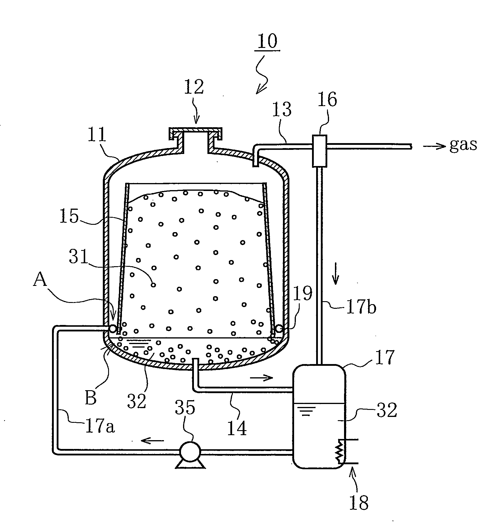
[0068]As shown in FIG. 1, gasifier 10 for a gas hydrate pellet according to the present invention includes a cylindrical body 15 disposed in a container 11. The cylindrical body 15 has a tapering form, so that its diameter gradually increases toward the bottom. Gas hydrate pellets 31 introduced through a supply inlet 12 at the upper portion of the container 11 are stored inside the cylindrical body 15. This cylindrical body 15 is made of a metal such as aluminum and stainless steel or made of a resin. The inner wall surface of the cylindrical body 15, which comes into contact with the pellets 31, is embossed so as to reduce the contact resistance with the pellets 31.

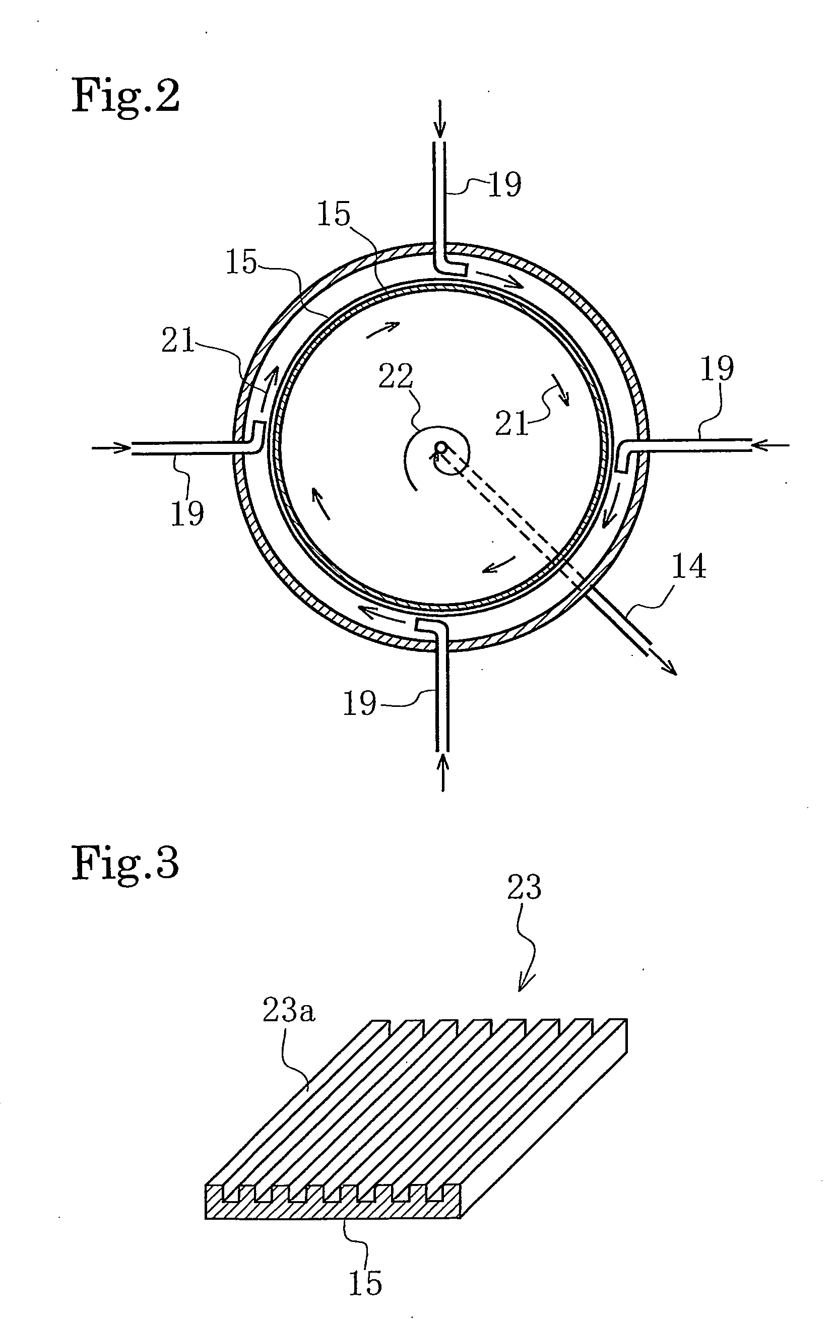
[0069]At a lower portion of the container 11, multiple nozzles 19 are provided to jet water 32. The water 32 is jetted through these nozzles 19 in the same circumferential direction, and the water 32 is swirled in the container 11. Moreover, a discharge pipe 14 is provided upright at the center of the bottom portion of t...

embodiment 2

[0076]In a gasifier 10 of this embodiment, a stripe body 23 as shown in FIG. 3 is formed on the inner wall of a cylindrical body 15. The stripe body 23 further prevents adhesion between the pellets 31 and the inner wall of the cylindrical body 15. The inner wall of the cylindrical body 15 may be covered by polytetrafluoroethylene in addition to the stripe body 23. Alternatively, a waved plate such as a corrugated plate can be used as the inner wall of the cylindrical body 15.

embodiment 3

[0077]In this embodiment, a gasifier 10 is loaded on a truck 36 as shown in FIG. 9, allowing the transfer to a place where the gas supply is needed. For example, the gasifier 10 is transferred to a disaster area or an isolated island by the truck 36. A gas-supply pipe 24 is connected to equipment or the like that uses the gas as its fuel. Thus, the gas supply is achieved.

[0078]In the gasifier 10, a single container 11 serves as both a carrying container and a gasification container. Thus, gasification is conducted freely at the carrying destination for the gas supply.

[0079]The present invention provides a gasifier: which is capable of carrying·gasifying a gas hydrate pellet in a single container; which controls the amount of gas generated by decomposition of the pellet; and furthermore which does not allow a bridge phenomenon to occur.


PUM

PropertyMeasurementUnit
boiling pointaaaaaaaaaa
temperatureaaaaaaaaaa
equilibrium temperatureaaaaaaaaaa

Abstract

A gasification apparatus is provided which enables gas hydrate pellets to be transported and gasified in the same vessel and enables a gas to be generated by pellet decomposition in a controlled amount. The apparatus is free from bridging. The apparatus includes a heat-in-saluted vessel main body and, disposed therein, a tubular structure which is open at the top and bottom. This tubular structure holds therein gas hydrate pellets obtained by compression-molding a gas hydrate produced by the hydration reaction of a raw-material gas with raw-material water. The tubular structure becomes wider in diameter from the upper opening toward the lower opening. A channel for passing a heat carrier therethrough has been disposed between the lower end of the tubular structure and the inner bottom surface of the vessel main body. The apparatus is further equipped, between the tubular structure and the inner wall surface of the vessel main body, with a nozzle which ejects the heat carrier in a circumferential direction for the vessel main body. The vessel main body has a discharge pipe for discharging the heat carrier ejected from the nozzle, the discharge pipe projecting upright from the inner bottom surface of the vessel main body.

Description

TECHNICAL FIELD[0001]The present invention relates to a gasifier for carrying and gasifying a gas hydrate pellet and to a method therefor.BACKGROUND ART[0002]Among fuel gases, particularly, natural gas (a gas mixture mainly consisting of methane gas, propane gas, or the like), when in a form of liquefied natural gas, has a volume reduced down to 1 / 600th of that in its gaseous state. Accordingly, natural gas is transported in the form of liquefied natural gas (hereinafter, LNG) from a producing area to a consuming area or other areas. An LNG carrier equipped with a tank covered and surrounded by a heat-insulating material is used for the transportation.[0003]However, aforementioned LNG has an extremely low boiling point of −162° C., and has a characteristic that LNG rapidly evaporates as the temperature increases. Thus, it is necessary to keep LNG under the extremely low temperature condition during transportation. For this reason, a dedicated container having a great cold-reserving ...

Claims


Application Information

Patent Timeline
Patent Type & Authority Applications(United States)
IPC IPC(8): C10J3/00
CPCC10L3/06C10L5/363C10L3/108
Inventor WATANABE, SHIGERUIMAI, SHINJISHINAGAWA, KAZUHIKO
Owner MITSUI ENG & SHIPBUILD CO LTD
Why Eureka
Try Eureka