Magnetic sensor

a technology of magnetic sensor and micro-magnetic field, applied in wave based measurement system, instruments, reradiation, etc., can solve the problems of difficult to measure a micro-magnetic field with high accuracy, high cost of squid, etc., and achieve the effect of simple device structure and convenient setting

Active Publication Date: 2010-12-30
COLUMBIA PEAK VENTURES LLC
View PDF8 Cites 17 Cited by
  • Summary
  • Abstract
  • Description
  • Claims
  • Application Information

AI Technical Summary

Benefits of technology

[0022]With the configuration, since the first gas and the second gas are injected into the same cell, the structure of the device is simpler than a case where the first gas and the second gas are injected into difference cells. In addition, when the first gas and the second gas are injected into difference cells, the alignments of the optical axis of the probe light and each cell have to be performed separately from each other, but when the first gas and the second gas are injected into the same cell, such alignment is completed for one time, and therefore, the setting becomes easy.

Problems solved by technology

However, the SQUID costs are high because a superconducting device or a Josephson device is used.
In addition, the SQUID needs an effort because it is necessary to frequently supply liquid helium or liquid nitrogen to a cooling system in order to maintain a low temperature environment.
However, in the Appl. Phys. B75, 605-612 (2002) and Appl. Phys. B76, 325-328 (2003), there is a case where a noise occurs when optical signals detected by the two photodetectors are converted into electric signals, and thereby causing difficulties to measure a micro-magnetic field with high accuracy.
In addition, since two photodetectors are used as detectors, the structure of a magnetic sensor is complicated and the calculation also becomes complicated.

Method used


Image

  • Magnetic sensor
  • Magnetic sensor
  • Magnetic sensor

Examples


Embodiment Construction

[0029]Hereinafter, an embodiment of the invention will be described with reference to accompanying drawings. The embodiment is to show an aspect of the invention, and the invention is not limited thereto. The invention can be arbitrarily modified within the scope of the gist of the invention. In addition, in the drawings below, the scales, the numbers, and the like of the structure are difference from those of the actual structure of the invention in order to provide easy understanding about the structure.

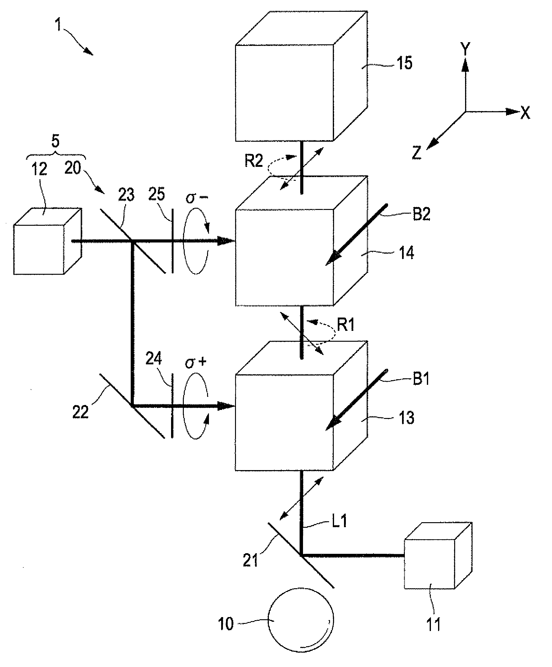
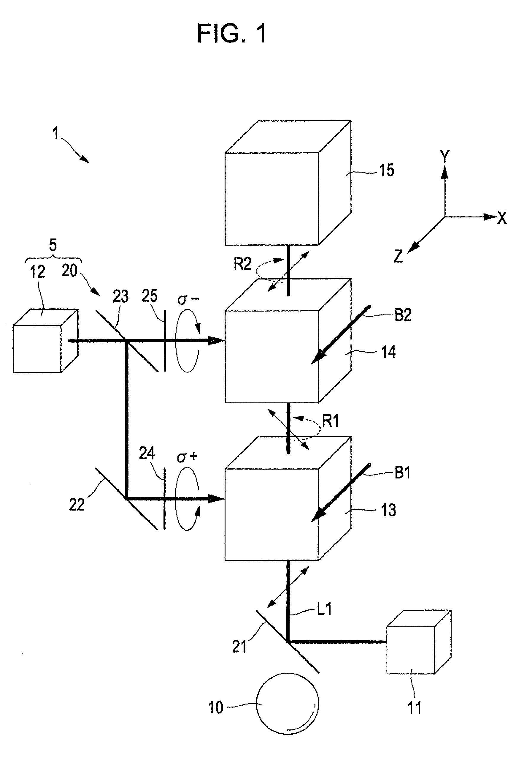
[0030]FIG. 1 is a schematic diagram showing the outline of the structure of a magnetic sensor 1 according to an embodiment of the invention. As shown in FIG. 1, the magnetic sensor 1 is an apparatus for measuring a measuring target magnetic field (a micro-magnetic field occurring from a magnetic field source 10, for example, cardiac magnetism or cerebral magnetism) using the optical pumping method (a method in which an electron spin of atoms is polarized using polarized light and t...


PUM


Abstract

A magnetic sensor for measuring a magnetic field using an optical pumping method includes a first gas in which a valence electron is composed of an odd number of atoms or ions, a probe light incidence device which causes first probe light including straight polarized light to be incident on the first gas, a second gas in which a valence electron arranged on an optical path of second probe light that is the first probe light transmitted through the first gas is composed of an odd number of atoms or ions, a pumping light incidence device which causes first pumping light including first circular polarized light to be incident on the first gas and second pumping light including second circular polarized light to be incident on the second gas, and a detector which detects a rotation angle of a polarization plane of the first probe light and a polarization plane of third probe light that is the second probe light transmitted through the second gas.

Description

BACKGROUND[0001]1. Technical Field[0002]The present invention relates to a magnetic sensor or the like.[0003]2. Related Art[0004]In the related art, a biomagnetism detecting apparatus has been known that measures a minute magnetic field occurring from a living subject, such as cardiac magnetism (magnetism coming from a heart), cerebral magnetism (magnetism coming from a brain), and the like. As such a biomagnetism detecting apparatus, for example, there is a Superconducting QUantum Interference Device (SQUID). Furthermore, the SQUID is a device (magnetic sensor) that can take variations of a slight magnetic field out as an electric voltage under a low temperature environment, by using, for example, a device (Josephson device) in which a thin portion (Josephson junction) is provided in a part of a superconducting device such as a superconducting ring, or the like.[0005]FIGS. 5A and 5B are schematic diagrams of magnetic flux detecting coils showing an example of the SQUID in the relat...

Claims


Application Information

Patent Timeline
Patent Type & Authority Applications(United States)
IPC IPC(8): G01R33/26
CPCG01N24/006G01R33/26G01R33/0322
Inventor NAGASAKA, KIMIO
Owner COLUMBIA PEAK VENTURES LLC
Why Eureka
Try Eureka