Anti-reflection sheet, display element and display device

a technology of display elements and anti-reflection sheets, applied in the direction of identification means, instruments, coatings, etc., can solve the problems of easy wear and tear of pyramid-shaped or conic projections, easy to see images, and easy to fall off, so as to improve the wear resistance and pressure resistance of projections without lowering optical properties, the effect of low haze value and low reflectan

Inactive Publication Date: 2010-12-30
SOKEN CHEM & ENG CO LTD
View PDF6 Cites 25 Cited by
  • Summary
  • Abstract
  • Description
  • Claims
  • Application Information

AI Technical Summary

Benefits of technology

[0009]The present invention has been made in view of the above technical problems and aims to provide an anti-reflection sheet capable of improving wear-resis

Problems solved by technology

When external light such as sunlight or indoor illumination light reflects on a screen of a display device, contrast of the screen lowers, the screen becomes white and it becomes hard to view an image.
When a surface of the anti-reflection film is rubbed with a soft cloth or cleaner to wipe sebaceous matter, dirt deposited on the surface of the anti-reflection film, the pyramid-shaped or conic projections are easily worn down and crushed, and an anti-reflection function of the anti-reflection film is easily impaired.
Similarly, when the transparent protective plate is strongly pushed by a finger, the projections on the surface are crushed and the anti-reflection function is easily impaired.
Also in this case, when the transparent protective plate is pushed by a finger or a touch pad pen, the transparent protective plate comes into contact with the display element, and thus, in some cases, the projections of the anti-reflection film are crushed by pressure, and the anti-reflection function of the anti-reflection film is lowered and impaired.
However, in the case where the anti-reflection film having such prote

Method used


Image

  • Anti-reflection sheet, display element and display device
  • Anti-reflection sheet, display element and display device
  • Anti-reflection sheet, display element and display device

Examples


first embodiment

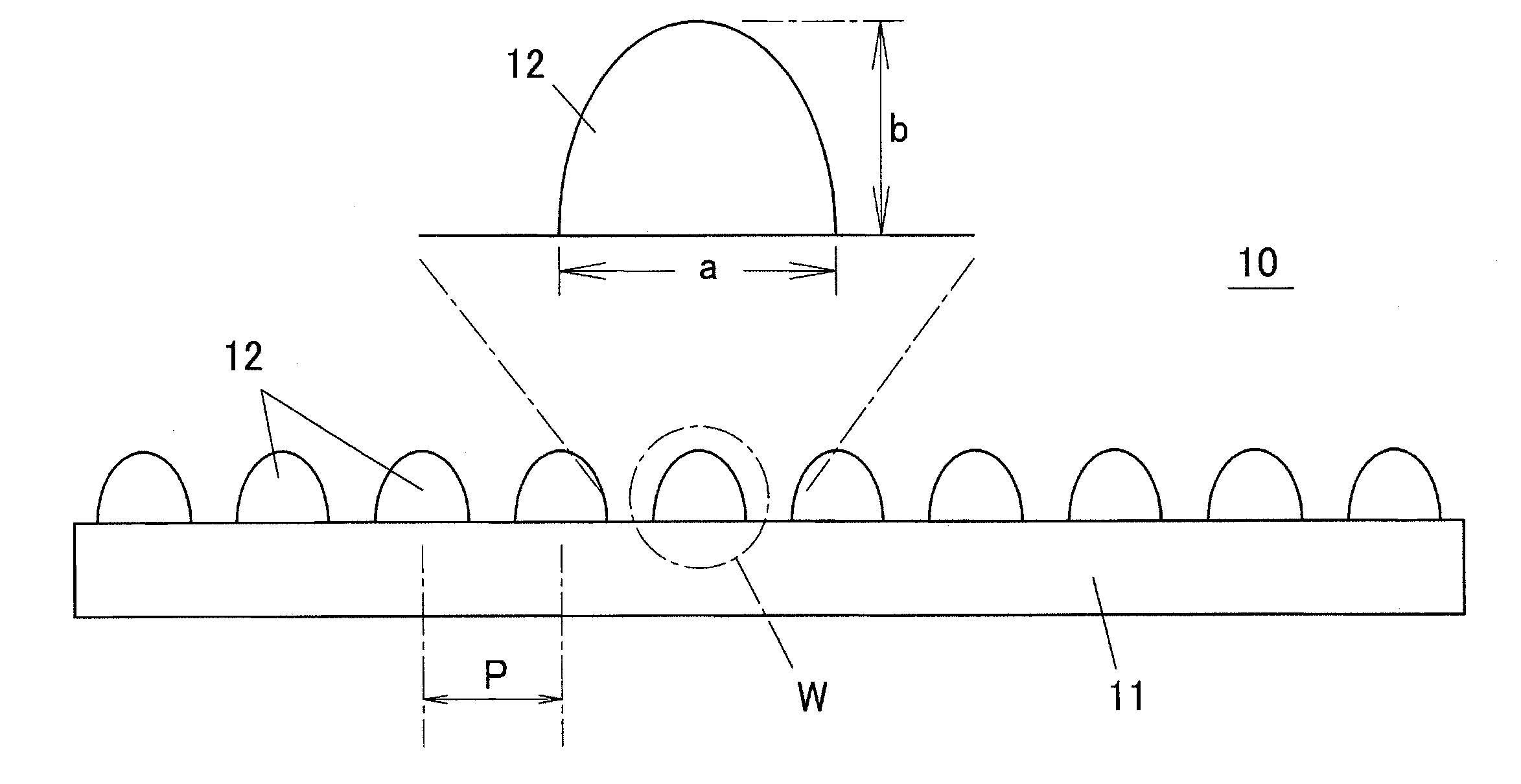
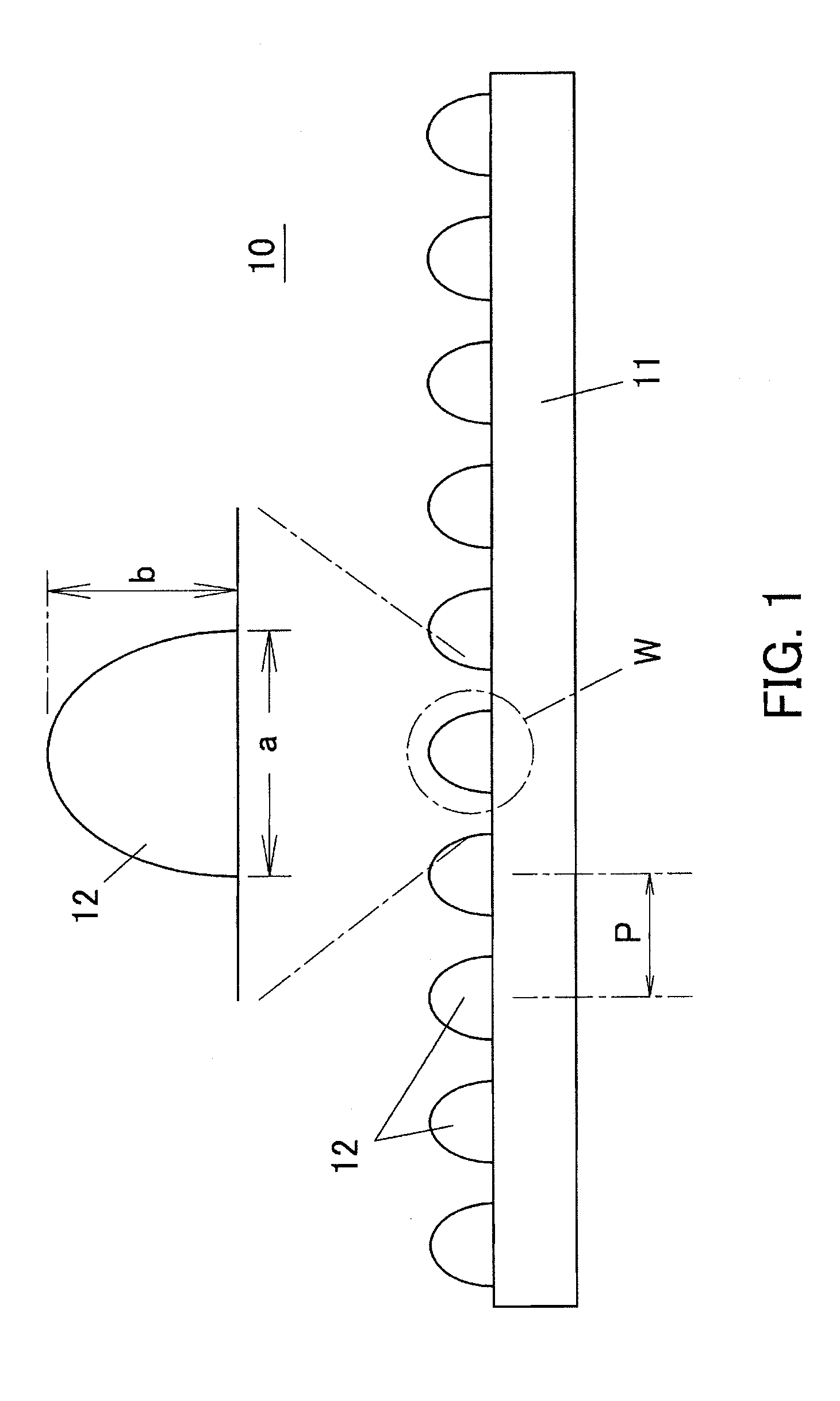
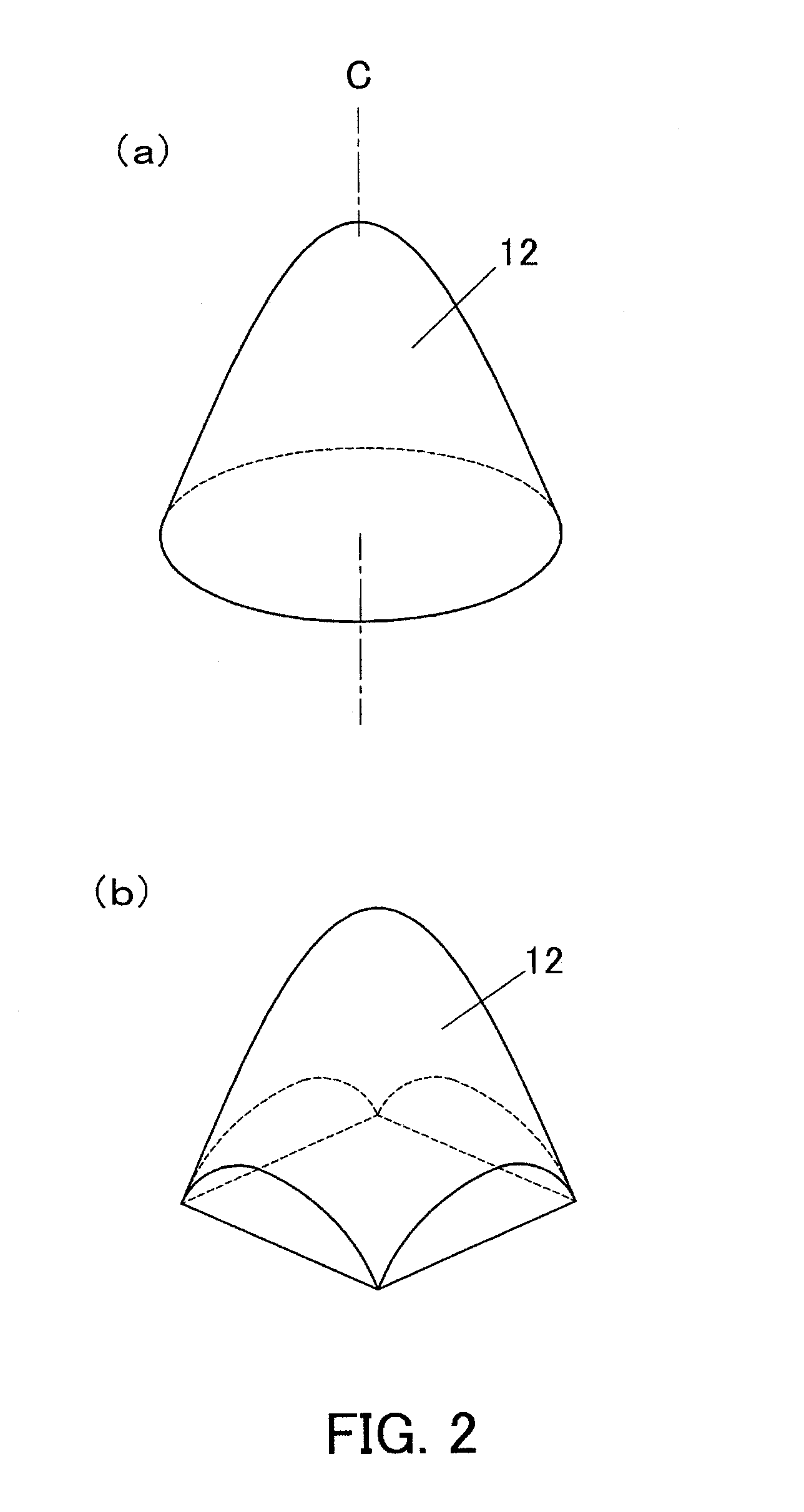
[0061]FIG. 1 is a schematic cross sectional view showing an anti-reflection sheet according to a first embodiment of the present invention, and FIG. 1 further shows an enlarged W portion thereof. FIG. 2(a) is a perspective view showing one shape of a projection provided on a surface of the anti-reflection sheet, and FIG. 2(b) is a perspective view showing another shape of the projection. FIG. 3(a) is a schematic plan view showing one example of arrangement of projections on a surface of a substrate, FIG. 3(b) is a schematic plan view showing another example of the arrangement of the projections, and FIG. 3(c) is a schematic plan view showing still another example of the arrangement of the projections.

[0062]As shown in FIG. 1, an anti-reflection sheet 10 is formed in a manner of bringing many transparent fine projections 12 (resin layer composed of only projections) into close formation on a flat and smooth surface of a transparent substrate 11. However, the projection 12 is shown ex...

second embodiment

[0092]FIG. 14 shows a shape of a cross section of a projection 12 used for an anti-reflection sheet according to a second embodiment of the present invention. The shape of the cross section of the projection 12 is in the shape of the quadratic function (parabola) in the first embodiment. However, in the second embodiment, a tip of the projection 12 is slightly wider than that of the quadratic function and wear-resistance and pressure resistance are higher than those of the projection 12 in the first embodiment.

[0093]As shown in this example, the cross section of the projection 12 is permitted to have a shape that the quadratic function shape is slightly deformed. Deformation is permitted so long as the wear-resistance and pressure-resistance of the projection 12 are not impaired, and a correlation coefficient R of the projection 12 may be 0.8 or more (the correlation coefficient R of the quadratic function itself is 1).

[0094]The correlation coefficient R of the shape of the cross se...

third embodiment

[0097]FIG. 16 is an explanatory view of a third embodiment of the present invention, and shows a cross section of a recess 16 having a quadratic function-shaped cross section. Although the anti-reflection sheet is adopted in the first embodiment in which the projections are formed on the substrate 11, also an anti-reflection sheet according to the third embodiment may be adopted in which the fine recesses 16 each having the quadratic functions-shaped cross section (rotational paraboloid) are closely formed. The aspect ratio and the other conditions of the projection 12 described in the first embodiment are also applied to the recess 16.

[0098]Also in the anti-reflection sheet in which the recesses 16 are formed, reflection of light can be suppressed similar to the anti-reflection sheet 10 in which the projections 12 are formed. When the recesses 16 are arranged at certain intervals, there is no possibility that the recess 16 is worn down and crushed compared with the projection 12. H...


PUM

PropertyMeasurementUnit
Fractionaaaaaaaaaa
Thicknessaaaaaaaaaa
Heightaaaaaaaaaa

Abstract

An anti-reflection sheet is formed in a manner of forming a resin layer, which has many fine projections 12, on a flat and smooth surface of a transparent substrate 11. Transparent resin is molded into the projections 12, the projections 12 have an almost quadratic function-shaped cross section including a center axis C perpendicular to the surface of the substrate 11, and a surface of the projection 12 is preferably a rotational paraboloid. A ratio (aspect ratio) b/a of a height b and width a of the projection 12 is 1 or less. Additionally, an arranged pitch P of the projections 12 is not more than half of a wavelength of incident light.

Description

TECHNICAL FIELD[0001]The present invention relates to an anti-reflection sheet, a display element and a display device. Specifically, the present invention relates to an anti-reflection sheet for preventing reflection of light in a specified wavelength band, and to a display element, such as an organic EL or liquid crystal display (LCD) panel, and a display device, the element and device having the anti-reflection sheet or sheets.BACKGROUND ART[0002]When external light such as sunlight or indoor illumination light reflects on a screen of a display device, contrast of the screen lowers, the screen becomes white and it becomes hard to view an image. In order to prevent such a phenomenon, an anti-reflection film has been conventionally proposed which is adhered to a surface of a display device and prevents reflection of external light.[0003]Such an anti-reflection film is disclosed in, for example, Japanese Published Unexamined Patent Application No. 2002-122702 (Patent Document 1). Th...

Claims


Application Information

Patent Timeline
IPC IPC(8): G02B1/11B32B7/02G02B1/118G02F1/1335G09F9/00
CPCG02B1/118G02F1/133502G02F1/133526G02B1/11H10K50/86G02B1/111G02B5/3025
Inventor SANARI, KOSUKEITO, YOSHINORIOKANO, ATSUSHITAKAGI, YOSHIHIKO
Owner SOKEN CHEM & ENG CO LTD
Why Eureka
Try Eureka