Dielectric film and semiconductor device using dielectric film

a dielectric film and semiconductor technology, applied in the direction of vacuum evaporation coating, transistors, coatings, etc., can solve the problems of hfo/sub>2 formed of a laminated film of tin and hfo/sub>2 also lack heat resistance, and achieve superior heat resistance and flatness, and the relative permittivity of the dielectric film according to the present invention does not decrease.

Active Publication Date: 2010-12-30
CANON ANELVA CORP
View PDF15 Cites 6 Cited by
  • Summary
  • Abstract
  • Description
  • Claims
  • Application Information

AI Technical Summary

Benefits of technology

[0026]The present invention has been made in consideration of the conventional problems described above, and an object thereof is to provide a dielectric film with a high relative permittivity, heat resistance with respect to an annealing treatment at 1000° C., and superior surface flatness, and a semiconductor device using the dielectric film.
[0027]An intense deliberation by the present inventors to resolve the problems described above has led to a discovery in that, with a dielectric film including a composite oxynitride containing an element A made of Hf, an element B made of Si, and N and O, by setting mole fractions B / (A+B+N) and N / (A+B+N) to specific ranges and by performing crystallization, superior flatness can be achieved in addition to a higher permittivity and heat resistance, which resulted in the present invention.
[0040]According to the present invention, a dielectric film with a high relative permittivity and superior heat resistance and flatness can be obtained. Therefore, the relative permittivity of a dielectric film according to the present invention does not decrease even when performing a high-temperature annealing process at 1000° C. or more. Consequently, even when the high-temperature annealing process is applied to a gate insulating film of a CMOS transistor element, a blocking insulating film of a non-volatile semiconductor device, or a capacitor insulating film of a DRAM element having a high-temperature annealing treatment process, an equivalent oxide thickness (EOT) can be reduced by higher permittivity.

Problems solved by technology

However, the techniques described above respectively have the following problems.
With the technique described in Non-Patent Documents 1 and 2 in which yttrium (Y), silicon (Si), lanthanum (La) or the like is doped as a metallic element on HfO2, it is shown that while an annealing treatment at 800° C. achieves crystallization and a higher permittivity at a relative permittivity of 30, relative permittivity drops to 20 or lower when an annealing treatment is performed at 1000° C. Therefore, HfO2 doped with Y, Si, or La is problematic in its lack of heat resistance with respect to an annealing treatment at 1000° C.
Therefore, cubic HfO2 formed of a laminated film of TiN and HfO2 also problematically lacks heat resistance with respect to an annealing treatment at 1000° C.

Method used


Image

  • Dielectric film and semiconductor device using dielectric film
  • Dielectric film and semiconductor device using dielectric film
  • Dielectric film and semiconductor device using dielectric film

Examples


first example (

Example Using Cosputtering)

[0103]A first example of the present invention will now be described in detail with reference to the drawings.

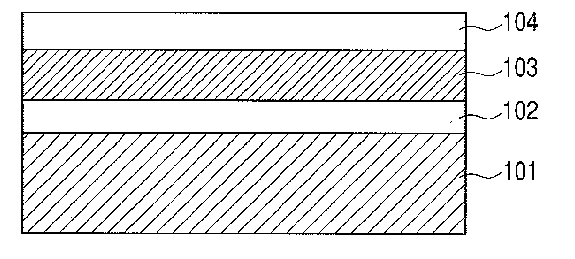
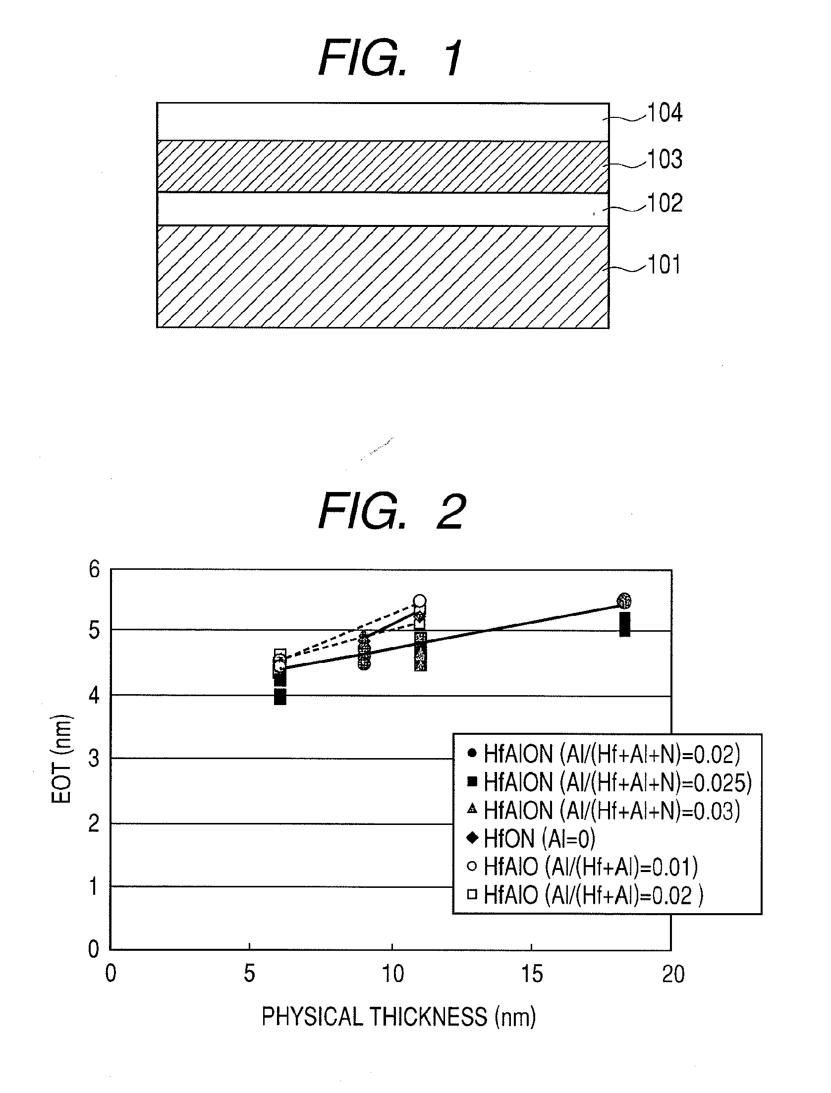
[0104]FIG. 1 is a diagram illustrating an MIS capacitor having the dielectric film 103. A HfAlON film was deposited by a sputtering method as the dielectric film 103 on the silicon substrate 101 having the silicon dioxide film 102 with a film thickness of 3 to 5 nm on a surface thereof. Metallic targets of Hf and Al were used as targets. Argon, oxygen, and nitrogen were used as sputter gases. In other words, a substrate processing apparatus according to the present example includes, in a first chamber thereof, a supplying mechanism that supplies a Hf target, an Al target, and a sputter gas into the first chamber. More specifically, the substrate processing apparatus according to the present example includes a first physical vapor deposition mechanism for performing physical vapor deposition such as sputtering using a Hf target and an Al target.

[010...

second example (

Example Using ALD Method and CVD Method)

[0124]The present example differs from the first example in that the dielectric film 103 is formed by a CVD method or an ALD method. Other formation processes are the same as the first example. Therefore, a substrate processing apparatus according to the present example includes a mechanism for realizing at least one of a CVD method and an ALD method such as a supplying mechanism that supplies an organic metallic material and an oxidant into a chamber.

[0125]A HfAlON film was formed as the dielectric film 103 by a CVD method or an ALD method at a range of 5 nm to 25 nm on the substrate 101 having the silicon dioxide film 102 on a surface thereof. A substrate temperature was set to 300° C., trimethylaluminum (Al(CH3)3) and tetrakis(diethylamino)hafnium (Hf[(C2H5)2N]4) were used as organic metallic materials, and H2O was used as an oxidant. The method of forming a dielectric film can be set by controlling a partial pressure of the oxidant to be i...

third example (

Example Applied to Gate Insulating Film)

[0137]A third example of the present invention will now be described in detail with reference to the drawings.

[0138]FIG. 16 is a diagram illustrating processes of a semiconductor device manufacturing method according to a third example of the present invention.

[0139]First, as depicted by process 1 in FIG. 16, a substrate processing apparatus according to the present example forms an element isolation region 302 on a surface of a silicon substrate 301 using a STI (shallow trench isolation) technique. The substrate processing apparatus according to the present example then forms a silicon dioxide film 303 with a film thickness of 1.8 nm on the element-isolated surface of the silicon substrate using a thermal oxidation method. Subsequently, the substrate processing apparatus according to the present example forms a HfAlON film with a film thickness ranging from 1 nm to 10 nm as a dielectric film 304 using the same method as the first example or t...


PUM

PropertyMeasurementUnit
relative permittivityaaaaaaaaaa

Abstract

The present invention provides a dielectric film having a high permittivity and a high heat resistance. An embodiment of the present invention is a dielectric film (103) including a composite oxynitride containing an element A made of Hf, an element B made of Al or Si, and N and O, wherein mole fractions of the element A, the element B, and N expressed as B / (A+B+N) range from 0.015 to 0.095 and N / (A+B+N) equals or exceeds 0.045, and has a crystalline structure.

Description

CROSS-REFERENCES TO RELATED APPLICATIONS[0001]This application is a continuation application of International Application No. PCT / JP2009 / 065305, filed on Sep. 2, 2009, the entire contents of which are incorporated by reference herein.[0002]This application also claims the benefit of priority from Japanese Patent Application No. 2008-282100 filed Oct. 31, 2008, the entire contents of which are incorporated herein by reference.TECHNICAL FIELD[0003]The present invention relates to a dielectric film and a semiconductor device using a dielectric film.BACKGROUND ART[0004]Developments in semiconductor devices are accompanied by increasingly higher degrees of element integration, resulting in increased miniaturization of each element and a reduction in operating voltage. For example, in the field of MONOS (metal oxide nitride oxide semiconductor)-type non-volatile semiconductor devices which include a blocking film that separates a charge retaining layer and a gate electrode, the miniaturiz...

Claims


Application Information

Patent Timeline
Patent Type & Authority Applications(United States)
IPC IPC(8): H01L21/31H01L21/314H01L21/336H01L21/8242B05D5/12C23C14/34H01L21/316H01L21/318H01L21/822H01L27/04H01L27/108H01L27/115H01L27/11521H01L27/11568H01L29/78H01L29/788H01L29/792
CPCH01L21/02178C04B2235/79H01L21/02194H01L21/02266H01L21/28185H01L21/28202H01L21/28273H01L21/28282H01L21/31604H01L28/40H01L29/513H01L29/518H01L29/6659H01L29/7833H01L29/7881H01L29/792C04B35/58007C04B35/581C04B2235/3865C04B2235/3886C04B2235/3895H01L21/02181H01L29/40114H01L29/40117
Inventor NAKAGAWA, TAKASHIKITANO, NAOMUTATSUMI, TORU
Owner CANON ANELVA CORP
Why Eureka
Try Eureka