
Variable Interleave Data Transmission

a data transmission and data technology, applied in the field of data transmission, can solve the problems of reducing data throughput, data transmitted over any type of transmission medium is subject to noise, and the interleave depth for an entire cable data network may not be optimal for all cms

Active Publication Date: 2010-12-30
TIVO CORP
View PDF8 Cites 21 Cited by
  • Summary
  • Abstract
  • Description
  • Claims
  • Application Information

AI Technical Summary

Benefits of technology

[0006]Some embodiments herein provide for dynamically setting interleave depths for various groups of devices, and / or for individual devices. The centralized network control system (e.g., a CMTS) may classify various data receiving devices (e.g., CMs) into various interleave depths. Where the data receiving device's (e.g., CM's) performance is monitored, embodiments may be configured to determine if increased noise is interfering with traffic, requiring a greater interleave depth. If noise has not affected traffic throughput, the interleave depth may be lowered for the specific data receiving device, lowering latency for that device.
[0010]Additionally, data may be provided for simultaneously storing more than one map where the map dynamically varies. The system may then provide instructions to the data receiving devices (e.g., CM) to switch over the new map upon receipt of a triggering event. In this way the interleave map may dynamically vary without interrupting the flow of data.
[0011]In some embodiments, the interleave depth associated with each data stream may be adjusted. Adjustments may be made in response to errors detected by the data receiving and / or a centralized network management system. Adjustments to the associated interleave depths may also be made in response to the interleave depths requested by other receivers on the network and / or other nodes in the network. For example, some cable lines may be above ground and subject to ice loads during winter storms. This may subject devices associated with those nodes to more severe error conditions. Further, a node may have a receiver that is on the way to failing. Again, devices associated with that node would require higher interleaved depths. The same burst error corrective measures would not be required for other nodes in the system that may have buried cables and / or properly functioning receivers. The present system allows adjustments on an individual receiver basis and / or on the basis of groups of receivers such as those associated with a node.

Problems solved by technology

Data transmitted over any type of transmission medium is subject to noise, which can reduce the data throughput.
But statically setting the interleave depth for an entire cable data network may not be optimal for all the CMs.
Lower interleave depths reduce latency, but may result in an unacceptably high level of unrecoverable packets due to burst noise for a subset of CMs.

Method used


Image

  • Variable Interleave Data Transmission
  • Variable Interleave Data Transmission
  • Variable Interleave Data Transmission

Examples


Embodiment Construction

[0027]In the following description of the various embodiments, reference is made to the accompanying drawings, which form a part hereof, and in which is shown by way of illustration various embodiments in which the features herein may be practiced. It is to be understood that other embodiments may be utilized and structural and functional modifications may be made without departing from the scope of the present disclosure.

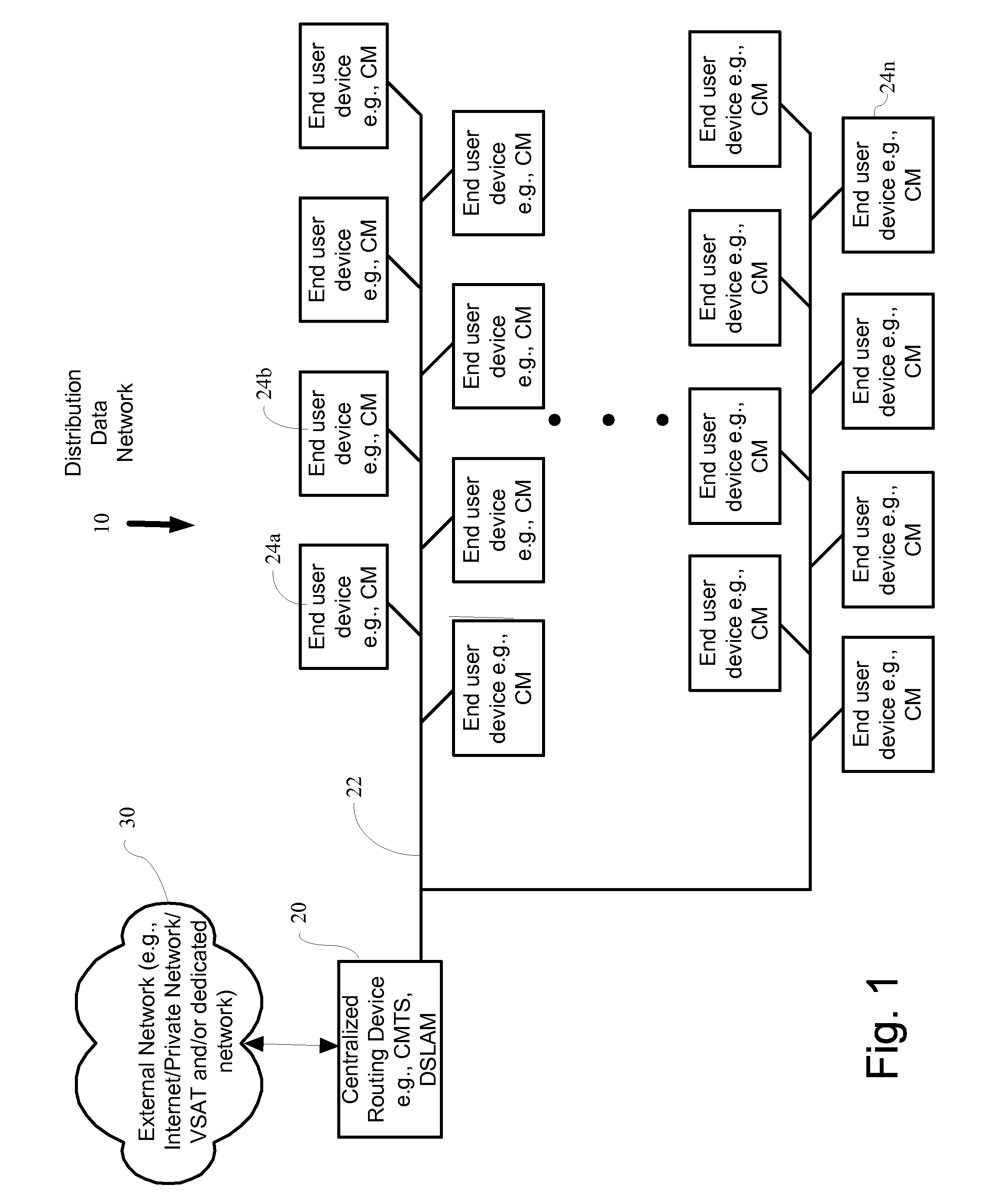
[0028]FIG. 1 illustrates an exemplary data distribution network (e.g., a cable network, DSL network, VSAT network, satellite network, wireless network) that may utilize embodiments of the features described herein. A centralized routing device 20 such as a cable modem termination system(CMTS) / DSLAM may be connected by a transmission medium such as a fiber, coaxial cable, wireless, or other transmission medium 22 to multiple modems (e.g., cable modems (CM)) 24 in subscriber locations, for example businesses or residences. Centralized router 20 may reside in the head...


PUM


Abstract

In cable modem termination systems (CMTS) and other information transmission systems, a method for changing the interleave depth associated with each data stream is provided. This may be done dynamically, and for any subset of downstream devices such as modems. The interleave depth may be set on an individual device level. Embodiments may decrease data receiving latency on devices that do not suffer from error rates, such as caused by burst noise, while maintaining throughput on devices with high error rates.

Description

FIELD OF THE DISCLOSURE[0001]The disclosure relates generally to data transmission. More specifically, the disclosure is directed towards data interleaving for data transmission.BACKGROUND[0002]Broadband data distribution systems are a popular way to deliver data to and receive data from a large number of buildings or residences in a geographic area. Examples of such systems are cable modem networks, fiber optic networks, and power system carrier signal distribution. For the example of cable modem systems, typically a head end unit such as a cable modem termination system (CMTS) is connected by coax cable to multiple (often several hundred) terminating cable modems for end users. The CMTS typically uses a protocol such as IP (Internet Protocol) to route data packets to specific cable modems on the cable data network.[0003]Data transmitted over any type of transmission medium is subject to noise, which can reduce the data throughput. Many techniques are used to reduce transmission er...

Claims


Application Information

Patent Timeline
IPC IPC(8): H03M13/27G06F11/10
CPCH04L1/0001H04L1/0025H04L1/0071
Inventor GILSON, ROSS O.
Owner TIVO CORP
Learn More