Composite material for geometric morphing wing

a technology of geometric morphing and composite materials, applied in the field of aeronautical vehicle systems, can solve the problems of compromising flight performance, mechanical surface systems, and limited ability of all devices to alter the shape, size and characteristics of airfoils, so as to increase the versatility of application and increase the flight control

Inactive Publication Date: 2011-01-06
THE BOEING CO
View PDF51 Cites 16 Cited by
  • Summary
  • Abstract
  • Description
  • Claims
  • Application Information

AI Technical Summary

Benefits of technology

[0012]This device has several advantages over existing airfoil member altering devices. One advantage is that an airfoil member is provided that is capable of significantly changing its size and shape. Versatility of the device also allows shape of the airfoil member to alter in compound manners. The ability to significantly change in size and shape provides increased application versatility and increased flight control throughout a flight envelope.
[0013]Another advantage is that it provides improved adaptability, improved flight characteristics including supporting greater payloads at lower speeds, and during take-off and landing, better aerodynamic characteristics at higher speeds, and increased flight range in comparison with traditional airfoil member altering devices that are limited in one or more of the above-stated characteristics.

Problems solved by technology

Aircraft that need to operate in several performance environments, however, often must compromise flight performance by using airfoil members that do not provide suitable characteristics in multiple environments rather than using airfoil members that are specifically designed for a particular flight situation.
However, all of there devices are limited in their ability to alter shape, size, and characteristics of the airfoil member; the airfoil member devices typically only modify a single aspect of the airfoil member, minimally affect airflow, or slightly modify shape of the airfoil member.
Furthermore, all of the above-stated devices tend to use motors or actuators and other mechanical components to perform minor changes in an airfoil surface.
These mechanical surface systems, however, typically only provide a very limited ability to affect airfoil member shape and aerodynamic flight characteristics of the aircraft.

Method used


Image

  • Composite material for geometric morphing wing
  • Composite material for geometric morphing wing
  • Composite material for geometric morphing wing

Examples


Embodiment Construction

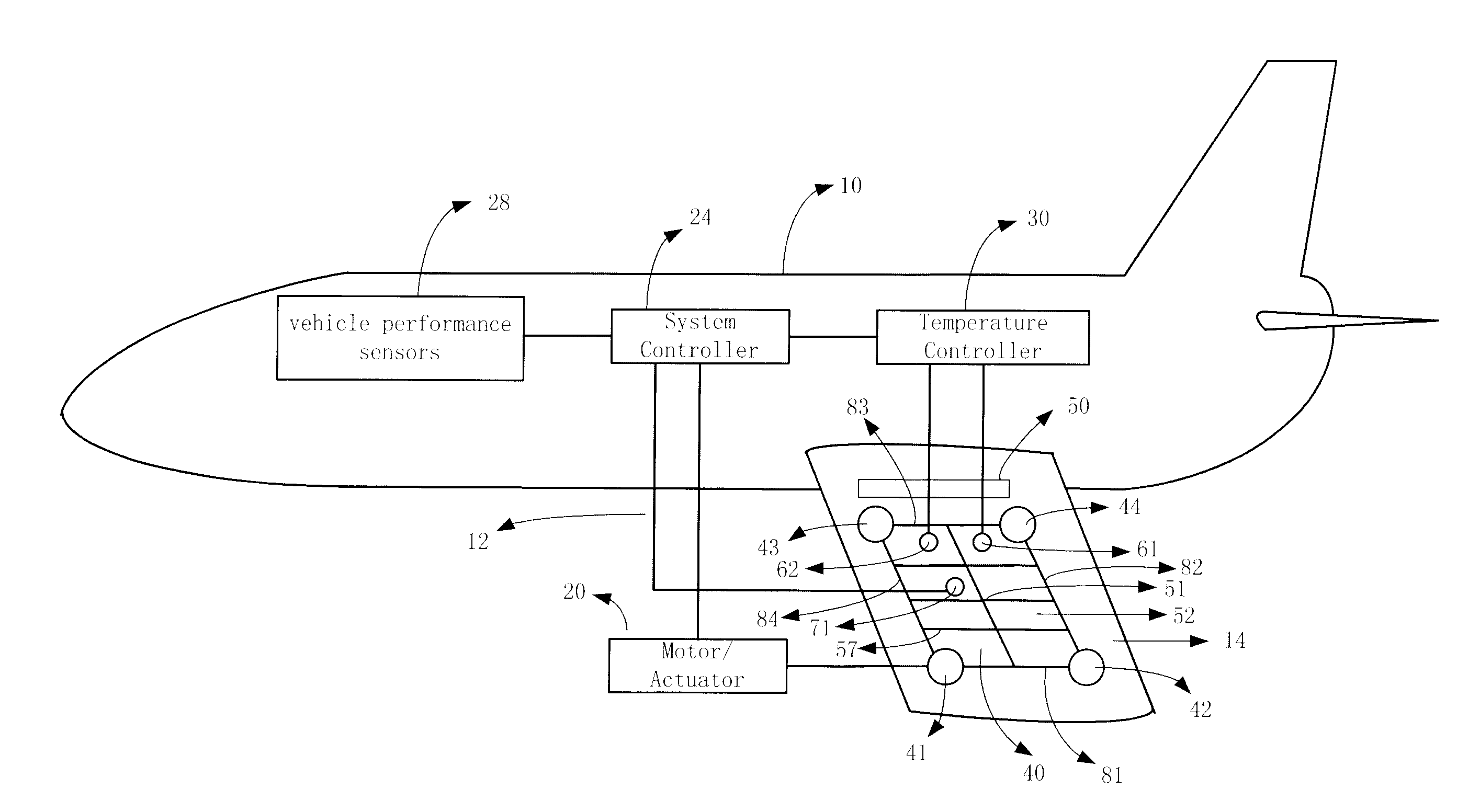
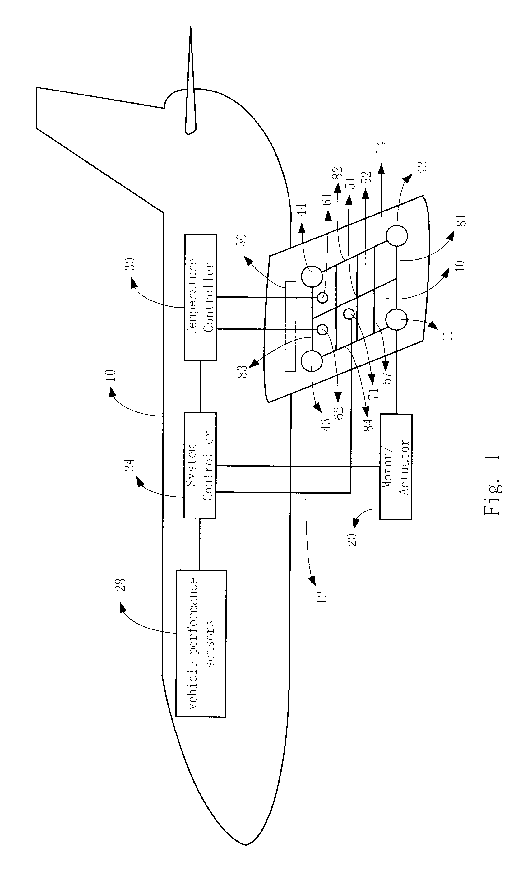
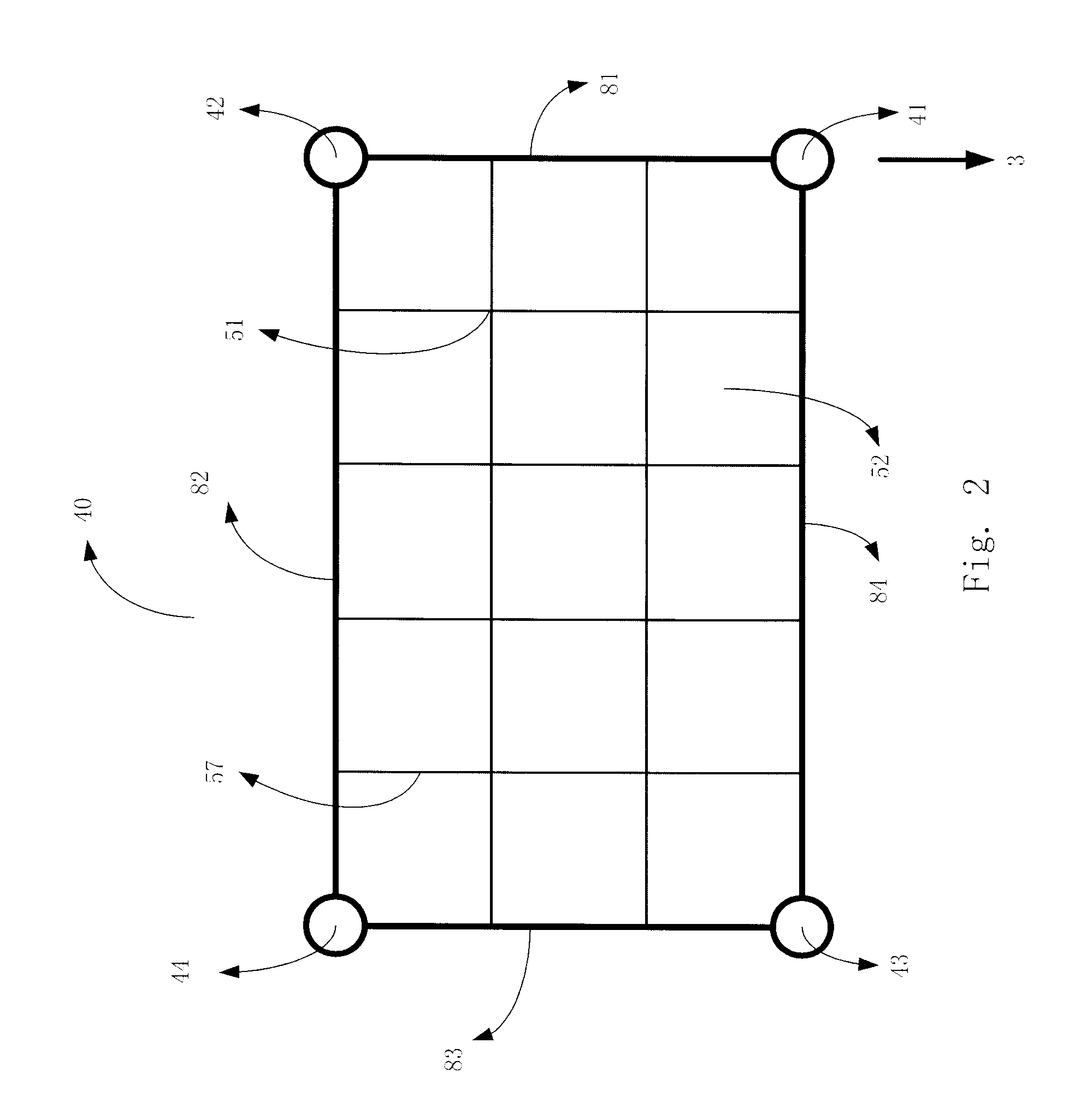
[0019]In each of the following figures, the same reference numerals are used to refer to the same components. While this application describes an apparatus, system, and method of altering size and shape of an airfoil member, the apparatus, system and method may be adapted for various applications including ground-based vehicles, aeronautical vehicles, including fixed wing and rotary wing aircraft, watercraft, and other applications known in the art that require the use of airfoil members. The apparatus, system and method may be applied to vertical stabilizers to increase control at lower speeds and to decrease drag at higher speeds, to winglets for modifying flight speed, and as well as to horizontal and canard surfaces. The apparatus, system and method may be applied to flaps and ailerons to modify shape of an airfoil member. The apparatus, system and method may also be used to modify flight control by changing the size and shape of a first airfoil in a first manner and by maintain...


PUM


Abstract

An airfoil member and an airfoil member altering system are provided for significantly modifying the shape and size of the airfoil member while simultaneously providing an airfoil member with increased adaptability to various flight conditions throughout a flight envelope. The airfoil member comprises at least one motor or actuator, a system controller, a plurality of vehicle performance sensors, at least one temperature controller and airfoil member comprising at least one geometric morphing device that is adjustable in both size and shape and one or more rigid members.

Description

RELATED APPLICATION[0001]This application is a divisional of U.S. patent application (Attorney Docket Number 06-0479, Ser. No. 11 / 612,244, filed Dec. 18, 2006) entitled “Composite Material for Geometric Morphing Wing,” which is related to U.S. patent application (Attorney Docket Number 02-1244, Ser. No. 10 / 357,022, filed Feb. 3, 2003) entitled “Fiber Matrix for a Geometric Morphing Wing”, both of which are incorporated by reference herein.FIELD OF THE INVENTION[0002]This application relates generally to aeronautical vehicle systems, and more particularly, to an apparatus, system, and method of altering the size and shape of an airfoil wing member.BACKGROUND OF THE INVENTION[0003]Airfoil members such as wings, horizontal and vertical stabilizers, canards, rotor blades, winglets, etc. are limited in ability to change their sizes and shapes so as to alter surfaces of the airfoil member and be adaptable to multiple flight conditions of a flight envelope.[0004]Currently, airfoil member s...

Claims


Application Information

Patent Timeline
Patent Type & Authority Applications(United States)
IPC IPC(8): B64C3/00
CPCY02T50/145B64C3/38Y02T50/10
Inventor HAMILTON, BRIAN K.HASSAN, AHMEDBIRCHETTE, TERRENCE S.MURRILL, ROBERT R.
Owner THE BOEING CO
Why Eureka
Try Eureka