
Light emitting diode package

a technology of light-emitting diodes and packages, which is applied in the direction of circuit thermal arrangements, solid-state devices, and semiconductor/solid-state device details, etc., can solve the problems of increasing thermal resistance, achieve excellent strength and heat dissipation properties, and improve mounting reliability , the effect of efficient production

Active Publication Date: 2011-01-06
ASAHI GLASS CO LTD
View PDF8 Cites 25 Cited by
  • Summary
  • Abstract
  • Description
  • Claims
  • Application Information

AI Technical Summary

Benefits of technology

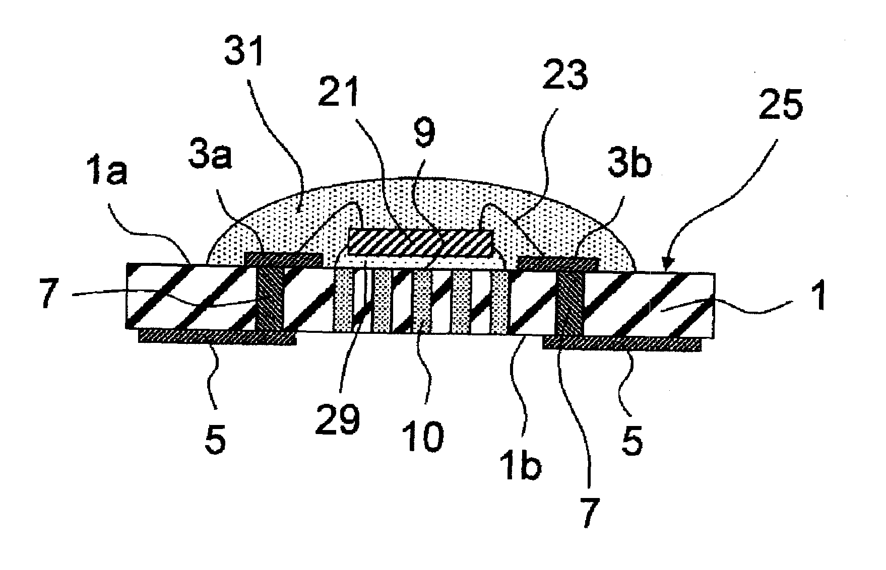
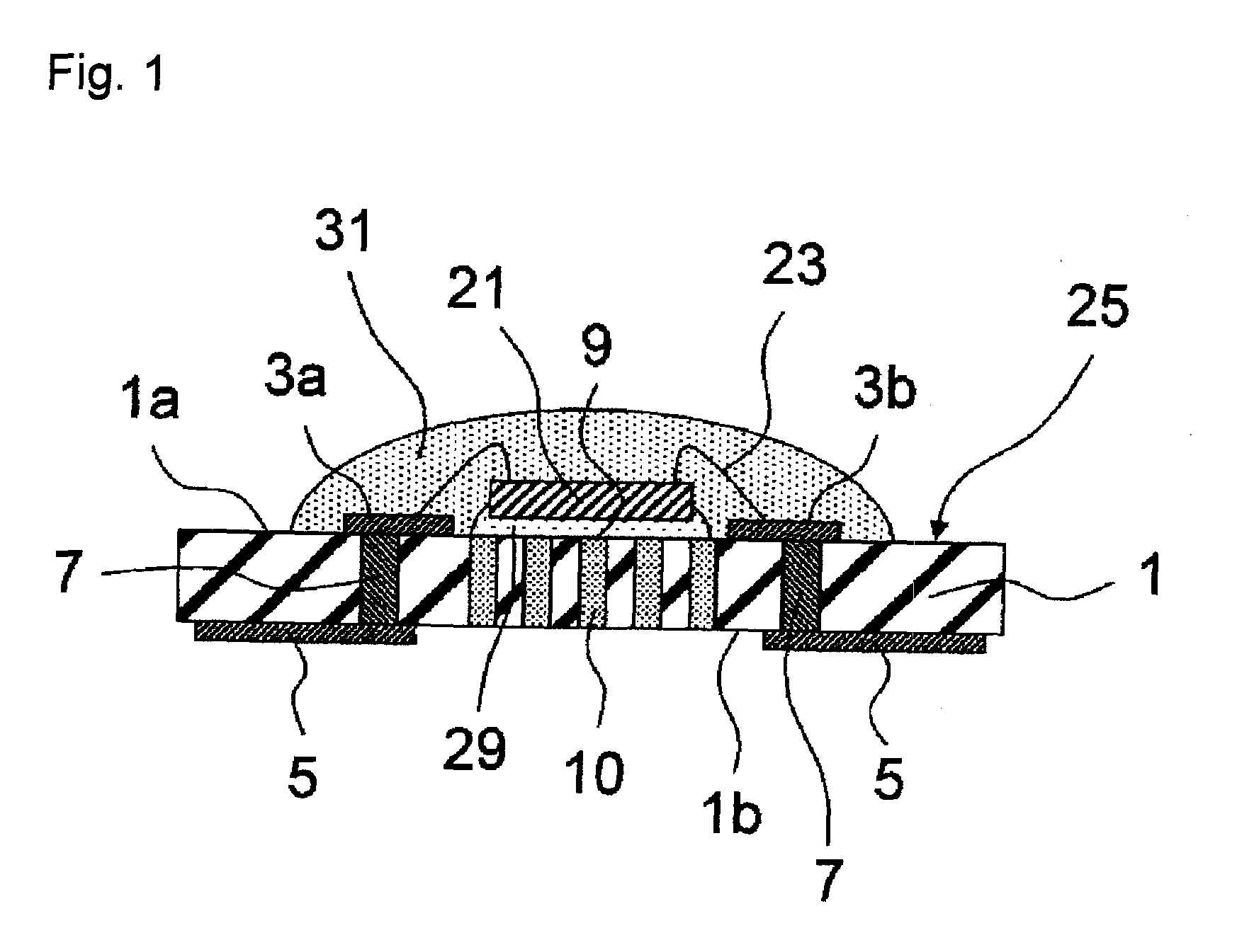
[0031]According to the present invention, an LED package with which the amount of protrusion of a through hole conductor is sufficiently small, and which is excellent in the strength and heat dissipation properties, can efficiently be produced.
[0032]Further, mounting reliability can be improved, whereby an LED package having high dimensional accuracy can be obtained.
[0033]Further, an LED package having high acid resistance can be obtained.
[0034]Further, in a case where a substrate is prepared by co-firing a silver conductor and a green sheet, an LTCC substrate may be deformed, for example, warped. This is mainly because of a difference in the shrinkage amount due to firing between a silver conductor paste and a green sheet. Further, it is also considered as follows. By elution of silver ions into the glass, the glass composition at a portion in contact with the silver conductor is changed, and resultingly, a portion far from the silver conductor and a portion in contact with the silver conductor differ in the shrinkage behavior.
[0035]According to the present invention, it is possible to obtain such an LED package that even when the substrate is warped at the time of co-firing, its warpage is small.
[0036]Further, coloring (silver coloring) may occur by the reaction of silver with glass contained in the raw material powder for the LTCC. This is considered to be caused by silver colloids which are formed by reduction of silver ions, which are eluted from the silver conductor into glass.

Problems solved by technology

However, if the protrusion of the thermal via is high, a large amount of the adhesive should be used, thus leading to an increase in the thermal resistance.

Method used


Image

  • Light emitting diode package
  • Light emitting diode package

Examples


examples

[0070]Now, the present invention will be described in further detail with reference to Examples, but it should be understood that the present invention is by no means restricted thereto.

[0071]In Examples 1 to 6 shown in Table 1 and in Example 10 to 15 shown in Table 2, raw materials were blended and mixed so as to achieve a composition represented by mol % in sections from SiO2 to ZrO2, and the mixed raw materials were put in a platinum crucible and melted at from 1,550 to 1,600° C. for 60 minutes, and then the molten glass was cast and cooled. The obtained glass was ground by a ball mill made of alumina using ethyl alcohol as a solvent for from 20 to 60 hours to obtain a powder of the glass.

[0072]Examples 1 to 6 are Examples of the present invention, and Examples 10 to 15 are Comparative Examples. Examples 7 to 9 are also Examples of the present invention, but no preparation of a powder of the glass as described above was carried out.

[0073]D50 (unit: μm) of each powder of the glass...


PUM

PropertyMeasurementUnit
mole percentageaaaaaaaaaa

Abstract

To provide a light emitting diode package of which the height of protrusion of a thermal via is decreased without decreasing the flexural strength of an insulating substrate.A light emitting diode package comprising a light emitting diode element mounted on a substrate, wherein the substrate is obtained by firing a glass ceramic composition containing a powder of glass containing, as represented by mole percentage, from 57 to 65% of SiO2, from 13 to 18% of B2O3, from 9 to 23% of CaO, from 3 to 8% of Al2O3 and from 0.5 to 6% of at least one of K2O and Na2O in total, and a ceramic filler.

Description

TECHNICAL FIELD[0001]The present invention relates to a light emitting diode package suitable for formation of illumination devices such as a light emitting diode device, a high brightness (HB) photodiode backlight, a light source related to displays, automobile illumination, decorative illumination, sign and advertisement illumination, and an information display, and an insulating substrate to be used therefor. Here, a light emitting diode package includes an insulating substrate on which a light emitting diode chip is mounted and a reflector, and will sometimes be referred to as a light emitting device in the present specification.BACKGROUND ART[0002]In recent years, along with a tendency to high brightness and whitening of a light emitting element such as a light emitting diode (hereinafter sometimes referred to as LED) device, a light emitting device employing LED for a backlight of a mobile phone, a large sized liquid crystal TV, etc. has been used.[0003]However, along with a t...

Claims


Application Information

Patent Timeline
Patent Type & Authority Applications(United States)
IPC IPC(8): H01L33/64H01L33/48
CPCC03C14/004C04B35/117H01L2924/0002C04B35/119C04B2235/36C04B2235/6025C04B2235/96H01L23/3677H01L33/486H01L33/641H01L33/642H01L2924/09701H05K1/0206H05K1/0306H01L2924/00
Inventor NAKAYAMA, KATSUYOSHIHISHINUMA, AKIHIROYANAGAWA, RUIORIHARA, KAZUYOSHIOSAKI, YASUKOIMAKITA, KENJIOOTSUKI, TAKASHIHAYASHI, HIDEAKIHONDA, SHINJI
Owner ASAHI GLASS CO LTD
Learn More