Temporary floating breakwater and causeway with simulated beach and kelp

a technology of causeway and temporary breakwater, which is applied in the direction of special-purpose vessels, vessel construction, groynes, etc., can solve the problems of inability to achieve the approach, the construction of conventional breakwaters is labor-intensive, and the approach is simply not feasible, so as to achieve the effect of sufficient size and suitable characteristics

Inactive Publication Date: 2011-01-06
WARWICK MILLS INC
View PDF10 Cites 10 Cited by
  • Summary
  • Abstract
  • Description
  • Claims
  • Application Information

AI Technical Summary

Benefits of technology

[0014]One general aspect of the present invention is a temporary floating breakwater which includes a plurality of inflatable modules and an encapsulating fabric cover configured for surrounding the inflatable modules when they are inflated, and thereby maintaining the inflatable modules in close proximity to one another. The floating breakwater when deployed is of sufficient size and has suitable characteristics for protecting shorelines and watercraft from waves having heights of more than 10 feet.
[0016]Various embodiments further include a rigid top deck of textile cells integral with the encapsulating cover and supportable by the plurality of inflatable modules so as to serve as a causeway. In some embodiments the plurality of inflatable modules can be deflated so as to temporarily sink the floating breakwater and thereby avoid damage due to surface hazards. And in certain embodiments each inflatable module includes a plurality of air-enclosing flotation bladders.
[0019]Another general aspect of the present invention is a temporary floating breakwater system which includes a plurality of inflatable floating breakwater support modules, an encapsulating fabric cover configured for surrounding the inflatable floating breakwater support modules when they are inflated, and thereby maintaining the inflatable floating breakwater modules in close proximity to one another, a floating causeway formed by a plurality of floating causeway modules and a causeway top surface which is supportable thereby, and a plurality of mooring lines and anchors configured for stabilizing a location of the floating breakwater and floating causeway when the floating breakwater and floating causeway are deployed on a body of water. The floating breakwater system when deployed is of sufficient size and has suitable characteristics for protecting shorelines and watercraft from waves having heights of more than 10 feet.

Problems solved by technology

The mass, logistics, and labor required to construct a conventional breakwater makes them impractical for remote areas.
This approach is simply not feasible when the quick establishment of a protected area is required.
A FBW by design is moored to a lee shore, which is an undesirable configuration for a floating object.
Under storm conditions, if mooring lines chafe or anchors drag, there is no space or time to respond.
A floating breakwater that is driven into the surf zone and pounded between the bottom and breakers will be a total loss.
In general, the design of a robust mooring system is the most important single issue in the design of a breakwater.
In contrast, the configuration of FIG. 4 has twice the system length and will be subject to very large mooring forces if there is significant along-shore current.
However the Army RIBs configuration reflects a large proportion of the wave energy and therefore reduces its mooring load.
This configuration shows the difficulty of satisfying all the current and wind preferences in a non-orthogonal situation of wind, shore, and current.
However the wind action on the moored ships is far from optimal.
However, the current adds to the mooring loads on the FBW.

Method used


Image

  • Temporary floating breakwater and causeway with simulated beach and kelp
  • Temporary floating breakwater and causeway with simulated beach and kelp
  • Temporary floating breakwater and causeway with simulated beach and kelp

Examples


Embodiment Construction

Main Tube and FBW Floats

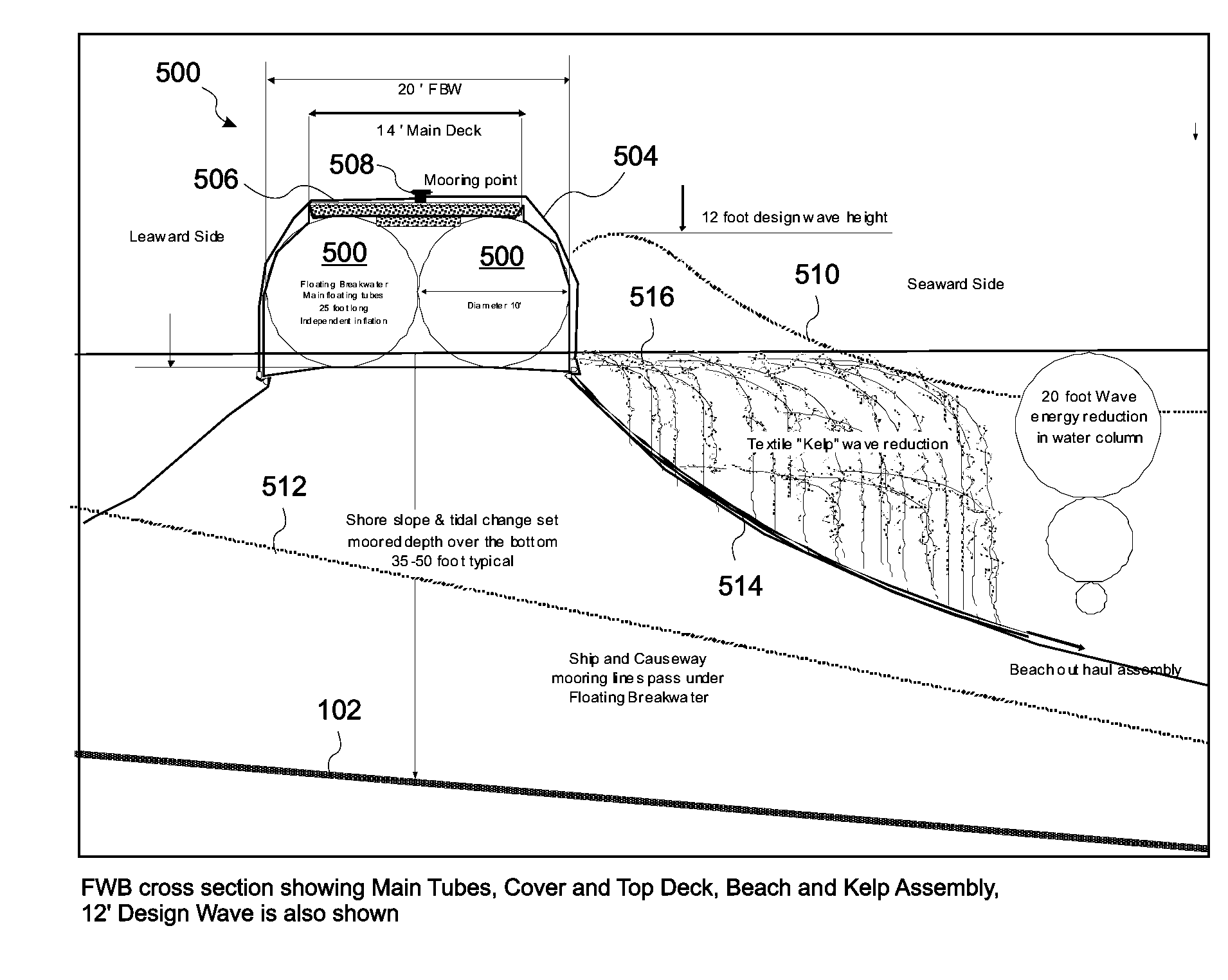
[0038]FIG. 5 is a cross sectional view of an embodiment of the present invention in which an inflatable floating breakwater (“FBW”) 500 is deployed at 300 feet. The total packed volume of the inflatable portion of this 300′ system as shown in the cross section of FIG. 5 can be packed in a single 20′ ISO container. The elimination of mechanical joints between inflated sections is a major feature of this approach, since hinges with solid pivot points are large, heavy, and prone to failure from wave action on a FBW. The embodiment of FIG. 5 also provides redundant flotation chambers 502 by enclosing a plurality of standard 10×25 ft floats 502 within a continuous cover layer 504. The cover layer 504 protects the inflated floats 502 and forms a textile flex point in the structure. This arrangement permits buckling of the assembly under extreme loads without damage. By staggering the float elements 502 in a second tube assembly 504 (i.e. the continuous cover layer)...


PUM


Abstract

A durable, quickly deployable temporary floating breakwater (FBW) can protect areas in austere locations. A plurality of inflatable modules is encapsulated within a common cover, which holds the modules together and in some embodiments supports a causeway thereupon. A separate floating causeway can be included. Embodiments include a semi-permeable “sloping beach” section which causes waves to break before reaching the FBW. A bed of wave-energy-absorbing synthetic kelp can be attached to the sloping beach. The beach and / or kelp can include low-surface-energy fibers and films, such as olefins and polypropylenes, to remove oil from the water in case of an oil spill or accident. In embodiments, the FBW can be temporarily sunk to avoid extremely high seas, ice, and / or other surface hazards. The FBW is lightweight, can be quickly and compactly stowed, and in some embodiments can be transported and deployed from the deck of an LCU 1610.

Description

RELATED APPLICATIONS[0001]This application claims the benefit of U.S. Provisional Application No. 61 / 222,230, filed Jul. 1, 2009, which is herein incorporated by reference in its entirety for all purposes.FIELD OF THE INVENTION[0002]The invention relates to marine deployable apparatus, and more particularly to temporary floating breakwaters.BACKGROUND OF THE INVENTION[0003]Permanent breakwater structures are offshore concrete or earthen revetments designed to provide coastal defense and mitigate shoreline erosion by absorbing and dissipating sea state intensity and surf conditions. They are often used to extend and enhance protection to harbors and seaports, and may also provide a secondary function as a causeway or travel corridor for land vehicles or foot traffic. The mass, logistics, and labor required to construct a conventional breakwater makes them impractical for remote areas. Temporary, floating breakwater designs have shown some successes. However, such structures typically...

Claims


Application Information

Patent Timeline
Patent Type & Authority Applications(United States)
IPC IPC(8): E02B3/06E01D15/14B63B21/00B63B21/50
CPCB63B21/50B63B22/02E02B3/062E01D15/14E01D15/24B63B35/44Y02A10/11
Inventor HOWLAND, CHARLES A.
Owner WARWICK MILLS INC
Why Eureka
Try Eureka