Device and method to sample and enrich impurities in hydrogen

a technology of impurities and devices, applied in the field of detection of impurities in fluids, can solve the problems of high cost of demonstration projects, high cost of sensitive instruments, and high laboratory time of skilled analytical chemists, and achieve the effects of facilitating the detection of contaminants, facilitating the analysis of hydrogen fuel, and facilitating the detection of low levels of trace species

Active Publication Date: 2011-01-13
UCHICAGO ARGONNE LLC
View PDF1 Cites 12 Cited by
  • Summary
  • Abstract
  • Description
  • Claims
  • Application Information

AI Technical Summary

Benefits of technology

[0017]Another object of the invention is to facilitate the detection of contaminants in hydrogen gas that can damage a fuel cell. A feature of the invention is that it is capable of enriching impurity concentrations. An advantage of the invention is that it facilitates detection of low levels of trace species, such as H2S, CO2, NH3, and CO, in fuel, while the fuel is maintained at pressures above atmospheric pressure, and before the fuel containing the species contacts the fuel cell. When combined with a detector, the invention provides an in situ signal point to move any fuel, which contains higher than allowable contaminant levels, to off line status.
[0018]Another object of the invention is to provide an apparatus and method to facilitate the analysis of hydrogen fuel on site of a vehicle fuel dispensing station. A feature of the instant invention is that the enrichment and analysis tools (detectors, sensors, etc.) may be located within a single portable unit. Another feature of the invention is that it is capable of storing enriched sample until analysis of the sample is required. An advantage of the instant invention is that it can provide indications of fuel quality within 2-60 minutes.
[0019]Yet another object of the instant invention is to provide an automated device for enriching impurities of a fuel to facilitate the determination of fuel quality. A feature of the invention is that with the enrichment device combined with a detector, the measurements can occur without user intervention. Inasmuch as the device provides a means for storing the enriched impurities, measurements of impurities can take pl

Problems solved by technology

These sensitive instruments are expensive, and they require considerable laboratory time of skilled analytical chemists.
The high cost of these analyses can be borne by the demonstration projects because of the large intervals between gas samples.
Some of the key factors that necessitate the development of new analytical technology for analysis of hydrogen are:Standardized methods for analysis of the trace species have not been defined and validated.Current methods requir

Method used


Image

  • Device and method to sample and enrich impurities in hydrogen
  • Device and method to sample and enrich impurities in hydrogen
  • Device and method to sample and enrich impurities in hydrogen

Examples


example 1

[0089]Based on a model for pressure swing-adsorption developed by the inventors, and disclosed in Papadias, D.; et al., Hydrogen quality for fuel cell vehicles—A modeling study of the sensitivity of impurity content in hydrogen to the process variables in the SMR-PSA system. International Journal of Hydrogen Energy 34, 6021-6035 the entirety of which is incorporated by reference, a numerical experiment was performed to investigate the range of concentrations and pressures for which the adsorption process deviates from linearity.

[0090]A gas containing 2 ppm of CO in hydrogen was fed to a vessel filled with activated carbon after which the CO was adsorbed at various pressures. After saturation, the pressure was reduced, allowing the CO to desorb, thereby causing the CO in the gas-phase to become enriched. The same calculation was repeated but adding N2, CO2 and CH4 at equal concentrations in the feed (a total concentration of 300 ppm means that each species in the feed is 100 ppm). Wh...

example 2

Membrane Concentrator Data

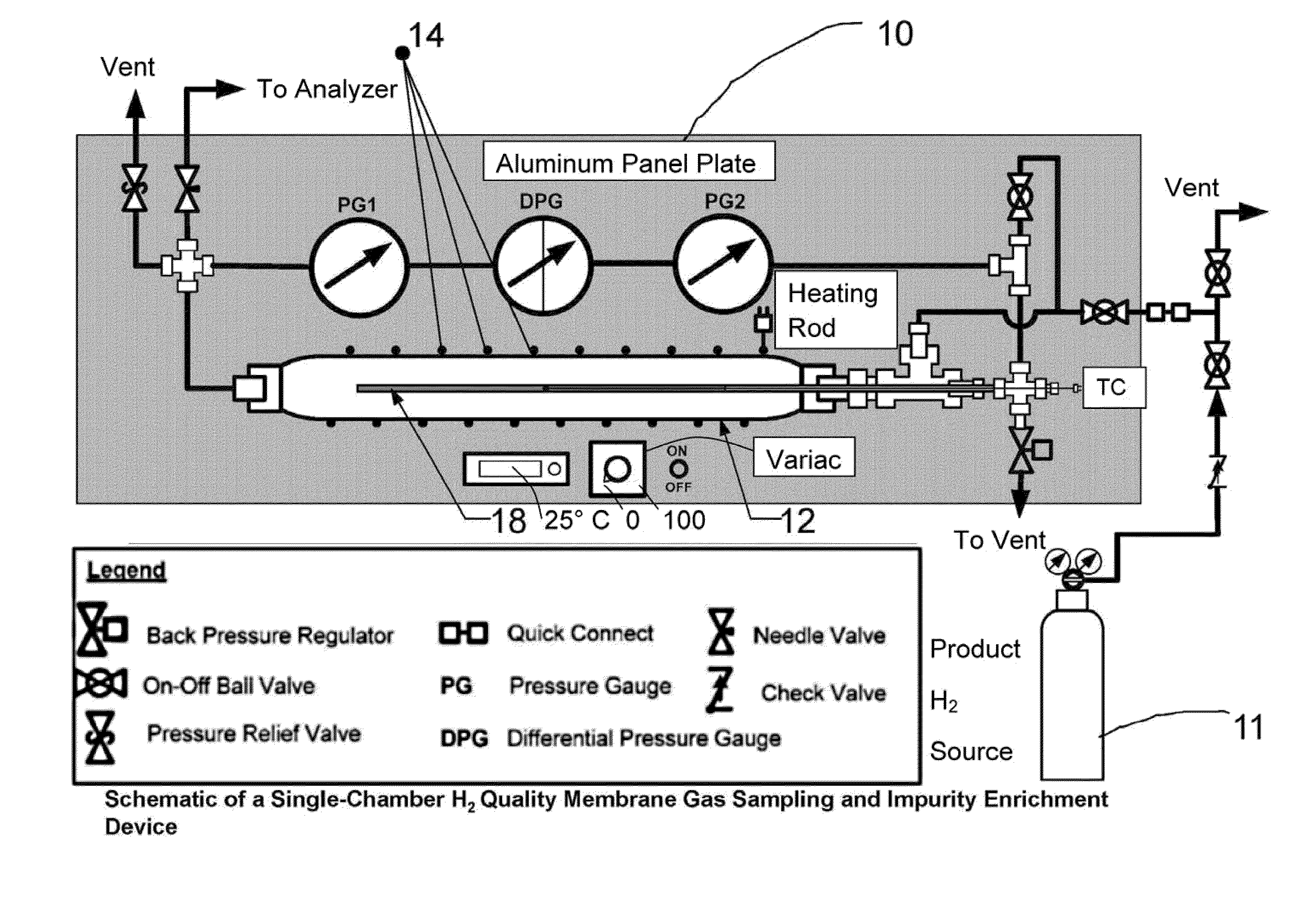
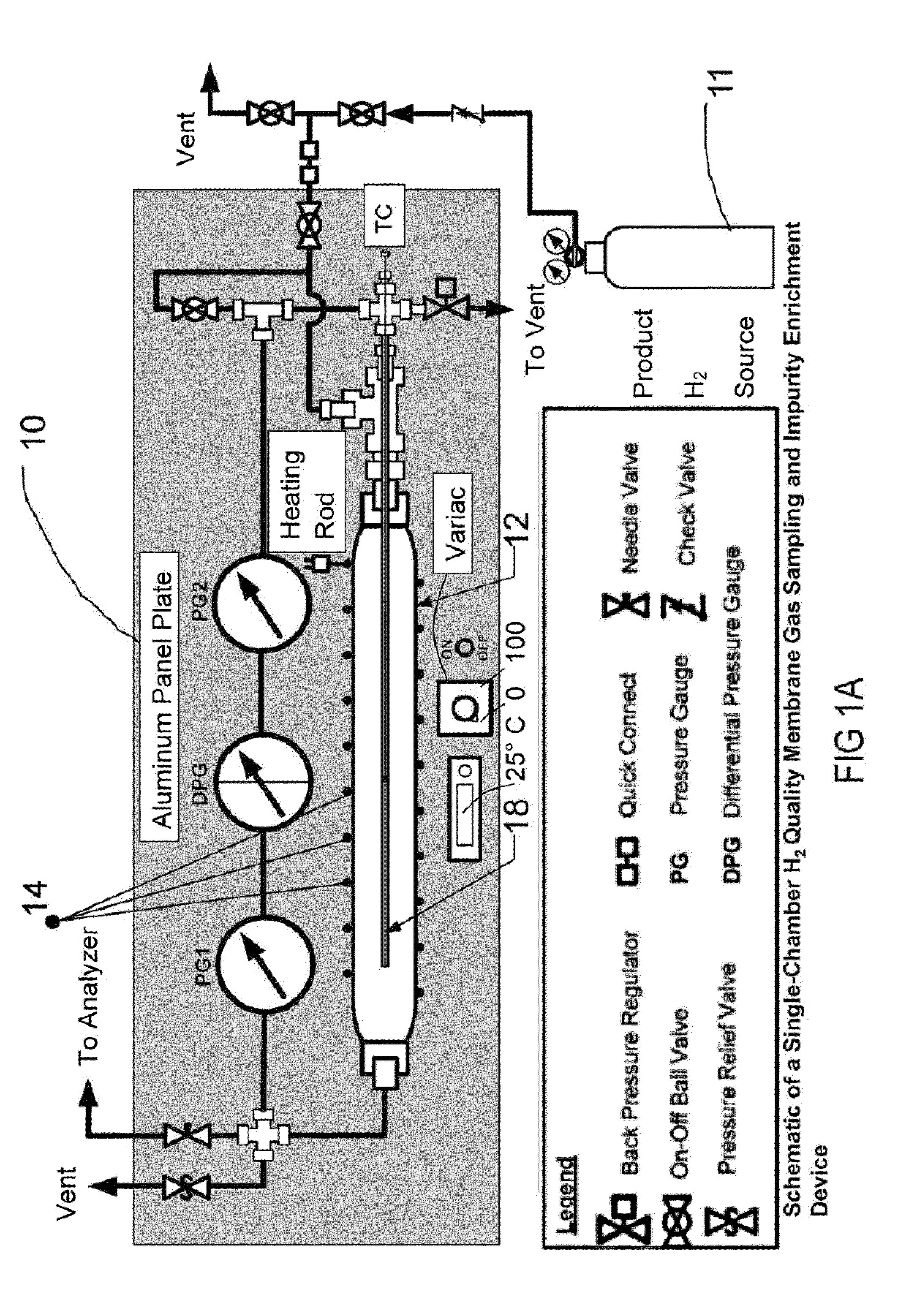
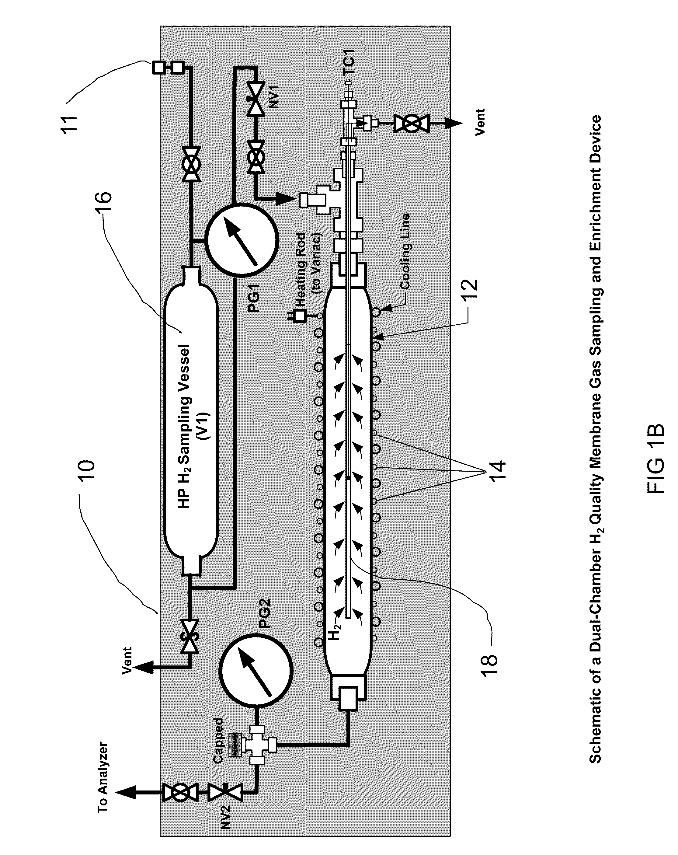
[0099]Turning to FIG. 1D, a high-pressure H2 sampling vessel, 16, rated for up to 1500 psig at room temperature, is used to collect a sample of hydrogen from a hydrogen gas source 11 for analysis. The sampling vessel 16 is connected to a second chamber, or volume, heretofore designated as the impurity concentrating vessel 12. In this particular example, the concentrating vessel 12 contains a Pd-alloy membrane tube. Hydrogen transport through the membrane is activated by raising the temperature of the membrane tube. The removal of hydrogen from the chamber results in higher impurity concentrations and a lower chamber pressure. The concentrating vessel obviates the need for separating or fractionating the trace species to be analyzed. No temperature cycle is needed to desorb the impurities. Also, desorption occurs without application of a high vacuum, which otherwise would make the process unsuitable for regular analysis in the field.

[0100]A series of tests w...

example 3

Adsorption Data

[0103]To demonstrate the proof-of-concept, an experimental apparatus was set up. FIG. 2B shows the schematic of the apparatus. In an embodiment of the adsorbent-featured system, the sorbent chamber 52 (having a volume of 50 mL) was packed with about 24 g of activated carbon (provided by Norit, Inc) while a downstream chamber 53 (10 mL) was left empty. Hydrogen gas containing 0.2% of each of the impurity species N2, CO, CH4, and CO, was passed through the two vessels at high pressure (700 psig) to adsorb the impurities.

[0104]Of the four impurity species, the sorbent was found to equilibrate (i.e., reach its capacity for adsorbing) successively to the concentrations of nitrogen, carbon monoxide, methane, and carbon dioxide in the feed gas. This sequence reflects the adsorption capacity of the carbon for the species, i.e., the carbon has a greater capacity for adsorbing CO2 than the other species. Approximately 200 liters of gas (containing 0.2% each of N2, CO, CH4, and ...


PUM


Abstract

Provided herein are methods and devices to enrich trace quantities of impurities in gaseous mixtures, such as hydrogen fuel. The methods and devices rely on concentration of impurities so as to allow the detection of the impurities using commonly-available detection methods.

Description

PRIORITY[0001]This utility application claims the benefits of U.S. Provisional Patent Application No. 61 / 224,968, filed on Jul. 13, 2009, the entirety of which is incorporated by reference.CONTRACTUAL ORIGIN OF THE INVENTION[0002]The U.S. Government has rights in this invention pursuant to Contract No. DE-AC02-06CH11357 between the U.S. Department of Energy and UChicago Argonne, LLC, as operator of Argonne National Laboratory.BACKGROUND OF THE INVENTION[0003]1. Field of the Invention[0004]The invention relates to the field of detection of impurities in a fluid. Specifically, the invention relates to an apparatus and method that facilitates the detection of minimal quantities of impurities in hydrogen fuel through concentration of the impurities by a known amount and subsequent measurement of the concentrated impurities. When coupled with an appropriate detector or sensor, the device can provide quantitative analysis (or concentrations) of the impurities in the original sample gas.[0...

Claims


Application Information

Patent Timeline
IPC IPC(8): G01N33/00
CPCG01N33/0014B01D53/04B01D53/22Y10T436/13B01D2053/221Y10T436/22B01D53/229
Inventor AHMED, SHABBIRLEE, SHELDON H.D.KUMAR, ROMESHPAPADIAS, DIONISSIOS D.
Owner UCHICAGO ARGONNE LLC
Why Eureka
Try Eureka