
Method and Apparatus of Space Elevators

Inactive Publication Date: 2011-01-13
HINTON GAYLEN R
View PDF0 Cites 10 Cited by
  • Summary
  • Abstract
  • Description
  • Claims
  • Application Information

AI Technical Summary

Benefits of technology

The construction of a space elevator according to the present invention will be faster, simpler and less costly than by using any prior art. Also, the operation of the present invention will allow a higher throughput of cargo to space, a lower energy use, and a faster time to orbit than with any previous space elevator designs. The cables of the present invention would move in a big loop from earth to geostationary orbit, and would provide an almost 100% efficient means of energy transfer. Huge motor / generators on the ground would power loads up the space elevator faster than any prior designs could ever do, and they would regeneratively recoup any energy from slowing down or descending loads.

Problems solved by technology

Not only do chemical rockets present serious safety concerns with the vast amounts of fuel and oxidizer, but the cost of sending cargo into space via chemical rockets is very expensive.
However, to date, the limiting factor that has kept a space elevator from being built has been the lack of suitable material with which to build the elevator cable.
Even if suitable cable materials had been available in the past, the prior art and previous designs may still have kept a space elevator from being built.
Existing designs have had very high costs for construction, and would not be very practical or economical to operate.
Prior art required massive accumulations of materials in space from multiple rocket launches, and the slow build-up of the space elevator by the means of climbers once a “seed” cable has reached the earth.
In addition, the throughput of cargo, per year, into space using climbers on a finished space elevator would be low.
However, laser powered climbers are, at best, only one or two percent efficient.
Also the motors, wheels, and energy conversion equipment for a climber comprise a large portion of the mass of the climber, which limits the cargo capacity.
In addition, climbers are inherently slow due to the power requirements and wheel limitations, and so the initial building and the ultimate operation of the space elevator would be slowed by both the speed and the cargo capacity of the climbers.
Another problem of previous designs is that the incremental cables lifted by the climbers to build the space elevator would always be dragging or sliding against the existing cable.
That friction and proximity create a high probability for a snag or tangled cables which would be very difficult to deal with.

Method used

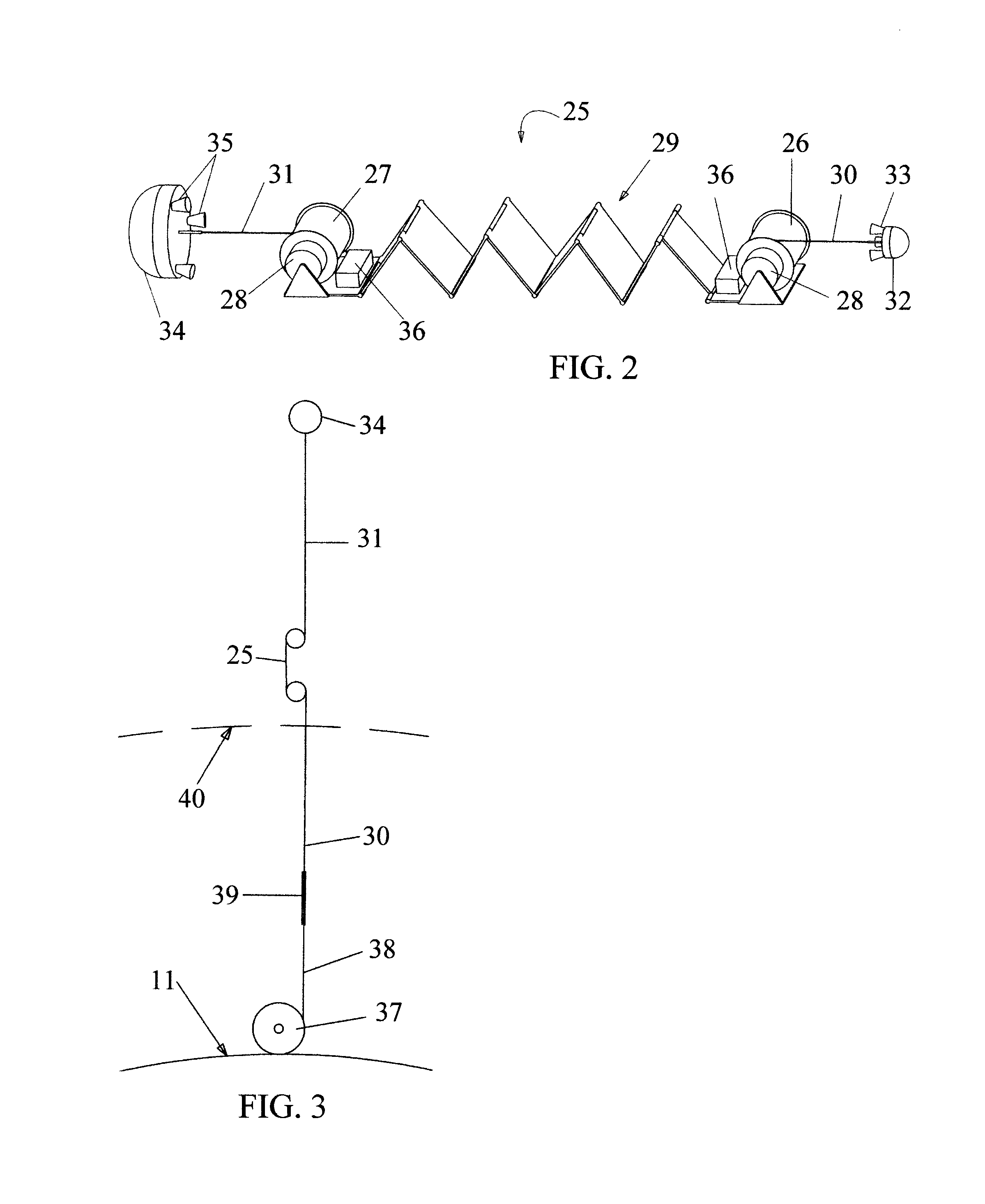

Image

  • Method and Apparatus of Space Elevators
  • Method and Apparatus of Space Elevators
  • Method and Apparatus of Space Elevators

Examples


Embodiment Construction

The following description is provided to enable any person skilled in the art to make and use the present invention, and sets forth the best modes contemplated by the inventor for using his invention. Variations to this description however, will be readily apparent to those skilled in the art, since only the generic principles of the present invention have been defined herein.

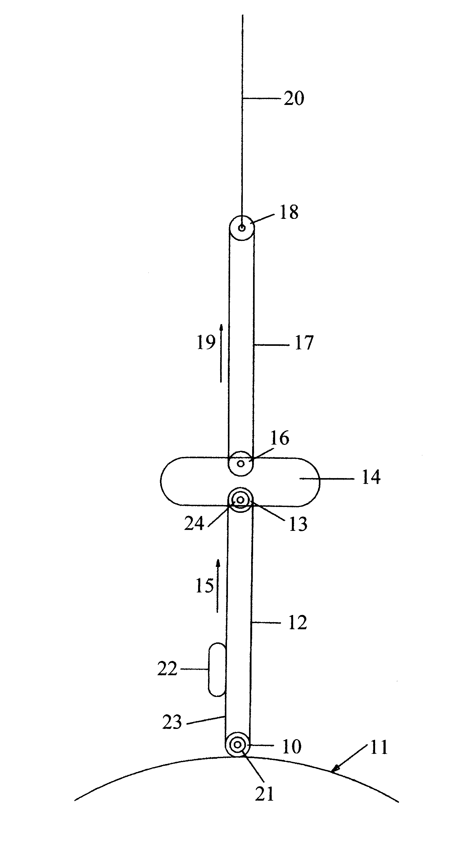
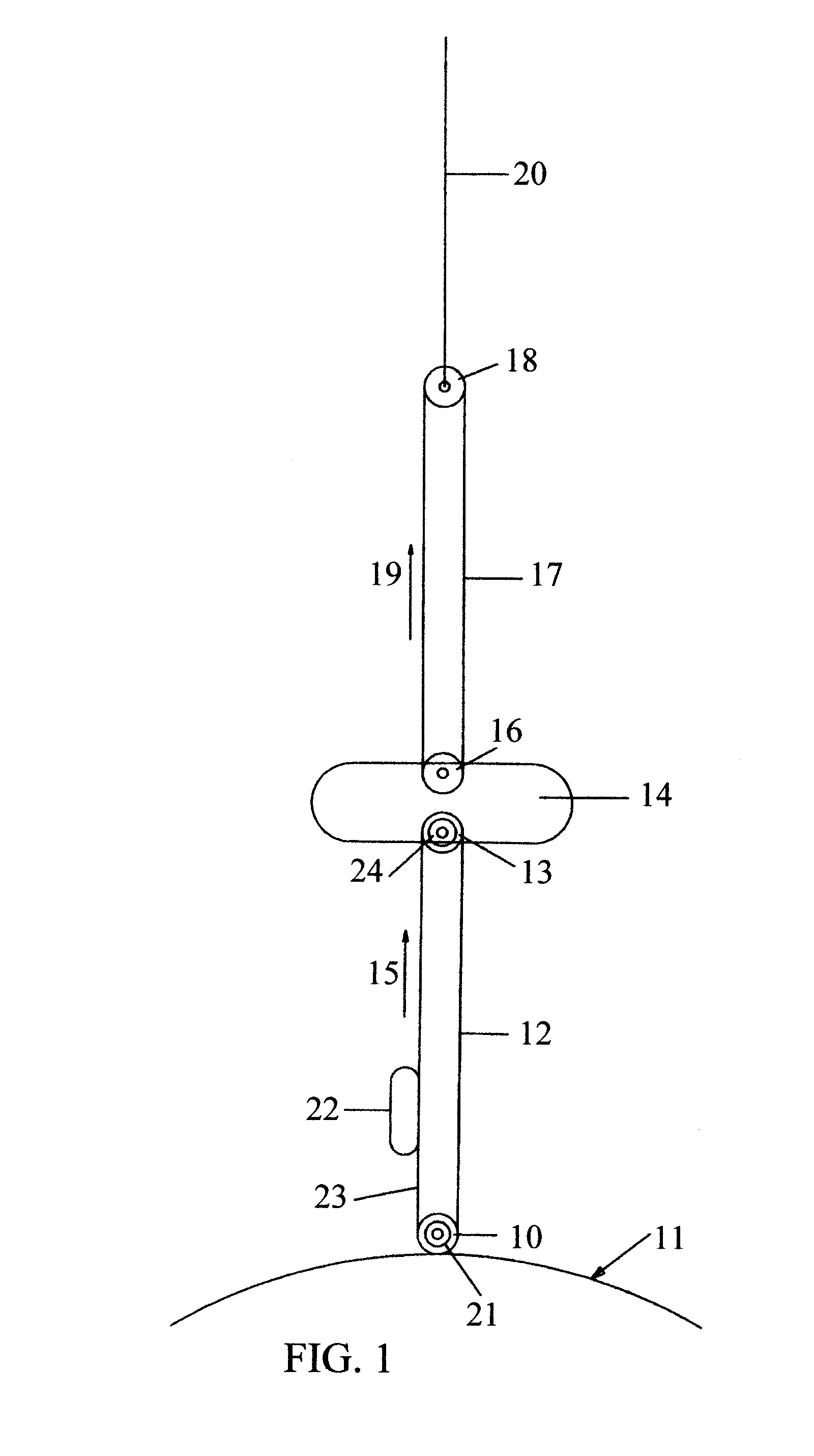
Referring now to FIG. 1, the space elevator of the present invention includes a pulley 10, securely fixed to the surface of the earth 11, at a location near the equator. A belt 12, is wrapped around pulley 10, and extends in a great loop from the surface 11 to a second pulley 13, located in space station 14, in geostationary orbit. Belt 12 rotates in the direction shown by arrow 15, and belt 12 is generally kept continually rotating in order that the Coriolis force, from the rotation of the earth, keeps the two opposite sides of the belt apart so that they cannot become entangled. Also located in space station ...


PUM


Abstract

A space elevator and method of construction of the same that allows a space elevator to be constructed with a single rocket launch by simultaneously sending cables down to earth and away from earth via a construction satellite. When the earthbound cable reaches the surface, additional cable of gradually increasing cross section is fed from the surface of the earth to finish the construction. The finished space elevator uses moving cables to transport simplified elevator cars into space, thereby greatly increasing the throughput of cargo into space compared to prior art and previous designs.

Description

BACKGROUND OF THE INVENTIONThe present invention relates to moving goods and people from the surface of the earth to outer space. Currently, all loads sent into space are transported via chemical rockets. Not only do chemical rockets present serious safety concerns with the vast amounts of fuel and oxidizer, but the cost of sending cargo into space via chemical rockets is very expensive. It can cost $5000 / kg or more to put cargo into low earth orbit, and $20,000 / kg to put cargo into geostationary orbit.An alternative to chemical rockets was put forth in 1960 by Yuri Artsutanov with the idea of a space elevator. The mathematical fundamentals for a space elevator were documented in 1975 by Jerome Pearson. However, to date, the limiting factor that has kept a space elevator from being built has been the lack of suitable material with which to build the elevator cable. Yet, recent developments with nanotubes and other allotropes and compounds of carbon or boron indicate that the lack of...

Claims


Application Information

Patent Timeline
IPC IPC(8): B66B7/00
CPCB64G1/002B64G5/00
Inventor HINTON, GAYLEN R.
Owner HINTON GAYLEN R
Learn More