Apparatus for carrying out improved control of rotary machine

Active Publication Date: 2011-01-13
DENSO CORP +1
View PDF19 Cites 27 Cited by
  • Summary
  • Abstract
  • Description
  • Claims
  • Application Information

AI Technical Summary

Benefits of technology

[0014]Specifically, the present invention aims at providing apparatuses for carrying out model predictive control of a rotary machine; these apparatuses are designed to

Problems solved by technology

These higher harmonic contents may adversely affect on the following capability of the actual

Method used


Image

  • Apparatus for carrying out improved control of rotary machine
  • Apparatus for carrying out improved control of rotary machine
  • Apparatus for carrying out improved control of rotary machine

Examples


Example

First Embodiment

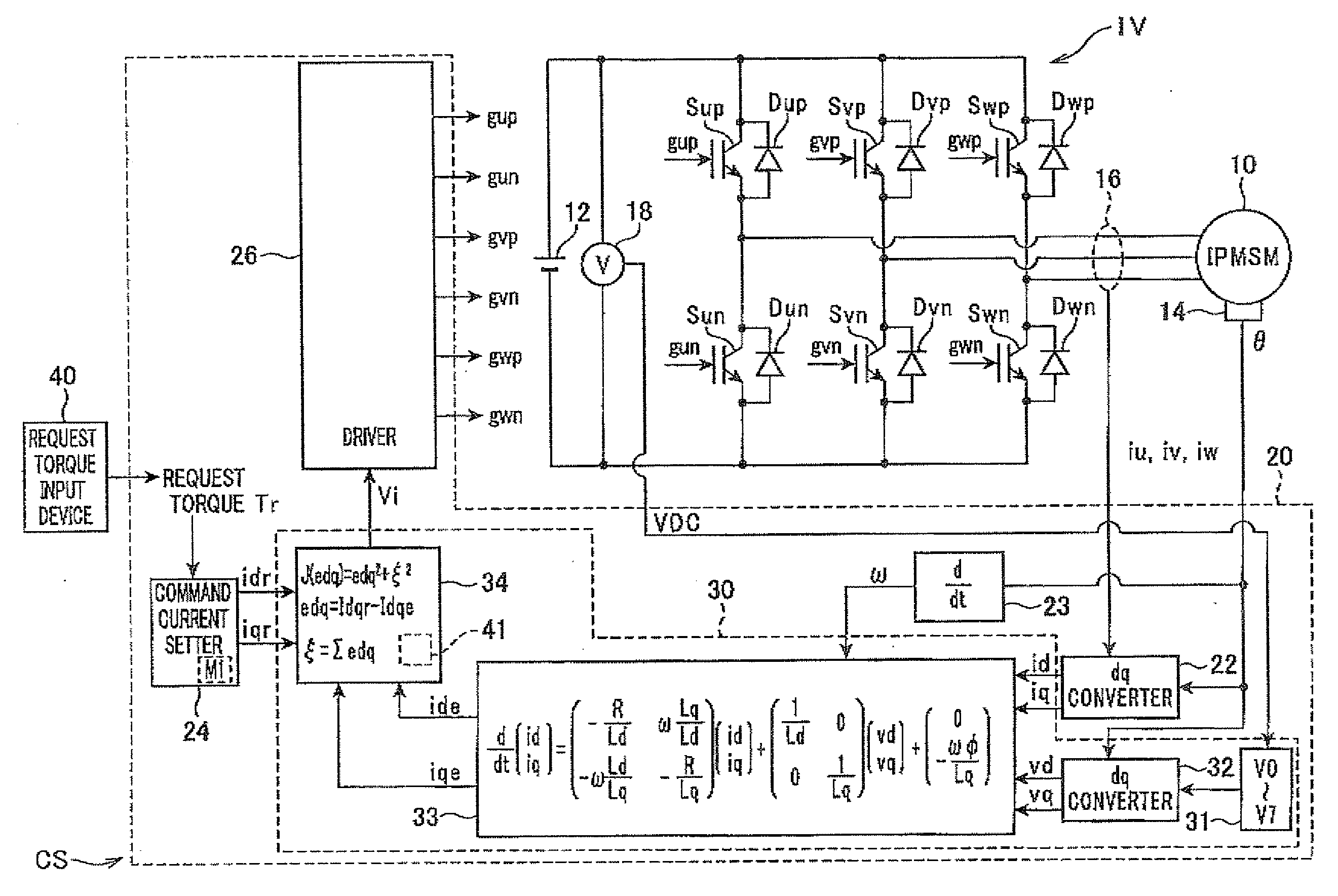
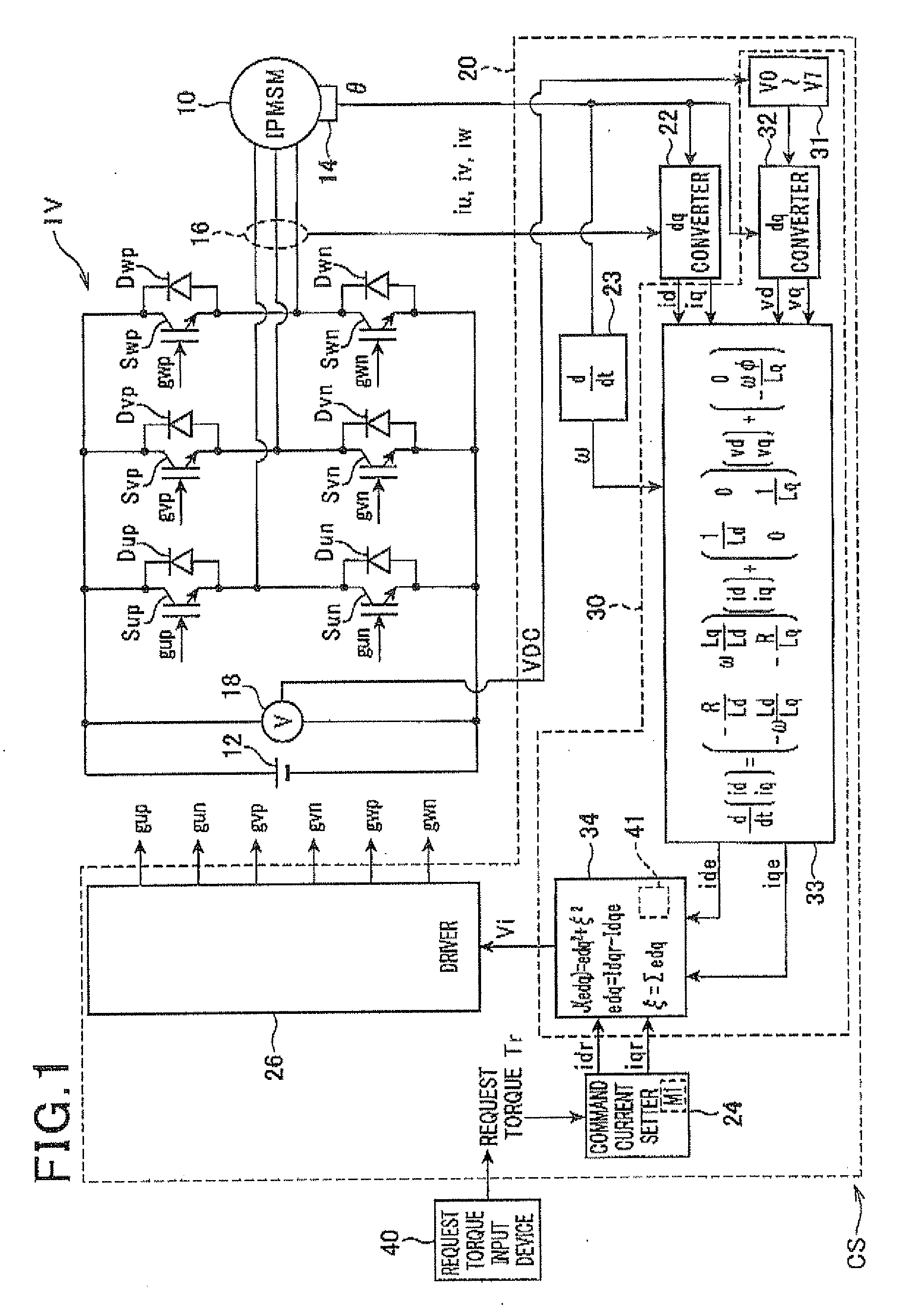
[0026]Referring to the drawings, particularly to FIG. 1, there is illustrated a three-phase motor-generator, referred to simply as “motor-generator (MG)”10 installed in, for example, a hybrid vehicle. In the first embodiment, as the motor-generator 10, an IPMSM (Interior Permanent Magnet Synchronous Motor) having a salient-pole structure is used.

[0027]In FIG. 1, there is also illustrated an inverter IV serving as a power converter, a high-voltage battery 12, a rotational angle sensor 14, current sensors 16, a voltage sensor 18, an interface (not shown), and a controller 20. The inverter IV, the battery 12, the rotational angle sensor 14, the current sensors 16, the voltage sensor 18, the interface (not shown), and the controller 20 provide a control system CS for the motor-generator 10.

[0028]Specifically, the motor-generator 10 and the high-voltage battery 12 can establish electrical connection therebetween via the inverter IV.

[0029]For example, the motor-generator 1...

Example

Second Embodiment

[0137]A control system CS1 according to the second embodiment of the present invention will be described hereinafter with reference to FIG. 5.

[0138]The structure of the control system according to the second embodiment is substantially identical to that of the control system CS according to the first embodiment except for the following different points. So, like parts and functional modules between the control systems according to the first and second embodiments, to which like reference characters are assigned, are omitted or simplified in description.

[0139]Referring to FIG. 5, the controller 20 includes a switching mode determiner 34A having a function that is slightly different from the function of the switching mode determiner 34 illustrated in FIG. 1. Specifically, the switching mode determiner 34A does not include the integral element 41 so that it does not add the square of the output ξ of the integral element 41 to the inner product edq2 in order to generate...

Example

Third Embodiment

[0147]A control system CS2 according to the third embodiment of the present invention will be described hereinafter with reference to FIG. 6.

[0148]The structure of the control system according to the third embodiment is substantially identical to that of the control system CS according to the first embodiment except for the following different points. So, like parts and functional modules between the control systems according to the first and third embodiments, to which like reference characters are assigned, are omitted or simplified in description.

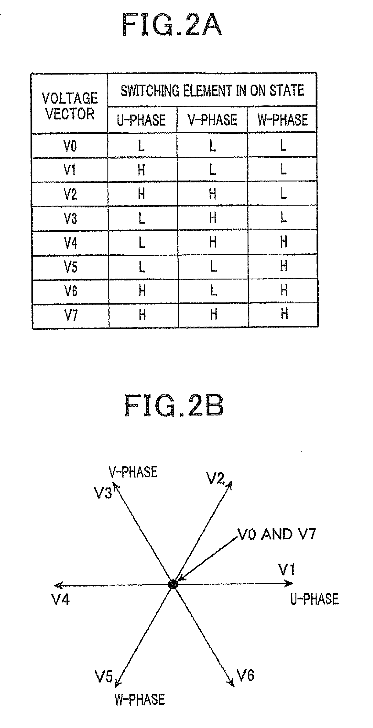
[0149]Each of the control systems CS and CS1 according to the first and second embodiments is designed to determine, according to the predicted d- and q-axis current values (ide, iqe) and the d-and q-axis command currents (idr, iqr), one of the eight switching modes (eight voltage vectors V0 to V7) for driving the inverter IV. Specifically, driving of the inverter IV in the selected one of the eight switching modes (eight...


PUM


Abstract

In an apparatus, a predicting unit uses, as an initial value of a controlled variable, at least one of a first measured value of the controlled variable and a second measured value of a physical variable expressed as a function of the controlled variable. The predicting unit predicts, based on the initial value of the controlled variable, a value of the controlled variable when a driving mode of a switching element of a power converter is set. A driving unit has an integral element and determines, based on an output of the integral element to which a deviation between the predicted value of the controlled variable and a command value of the controlled variable is inputted, an actual driving mode of the switching element to thereby drive the switching element in the determined driving mode.

Description

CROSS REFERENCE TO RELATED APPLICATIONS[0001]This application is based on Japanese Patent Application 2009-161481 filed on Jul. 8, 2009. This application claims the benefit of priority from the Japanese Patent Application, so that the descriptions of which are all incorporated herein by reference.FIELD OF THE INVENTION[0002]The present invention relates to apparatuses for driving a switching element of a power converter so that the switching element selectively establishes electrical connection and electrical disconnection between a terminal of a rotary machine and a voltage application unit for applying a plurality of different voltage levels to the terminal of the rotary machine through the power converter. The drive of the power converter controls a controlled variable of the rotary machine.BACKGROUND OF THE INVENTION[0003]A type of such control apparatuses set forth above is designed to carry out current feedback control to thereby adjust an actual value of at least one controll...

Claims


Application Information

Patent Timeline
IPC IPC(8): H02P6/08H02P21/00H02P21/14H02P21/18H02P21/22H02P21/24H02P23/14H02P27/04H02P27/06H02P27/08H02P27/12
CPCH02P6/08H02P23/14
Inventor IMURA, AKIHIROFUJITSUNA, MASAMIYOSHIDA, HIDEJIISHIDA, MUNEAKIZANMA, TADANAO
Owner DENSO CORP
Why Eureka
Try Eureka