Coil Component And Method For Manufacturing Coil Component

a technology of coil components and components, applied in the field of coil components, can solve the problems of large scale production facilities, increase in facility costs, and inability to mold complex shapes of cores, and achieve the effects of improving not only the impact resistance capability, preventing the cracking of cores, and improving the impact resistance capability

Inactive Publication Date: 2011-01-13
SUMIDA CORP
View PDF8 Cites 45 Cited by
  • Summary
  • Abstract
  • Description
  • Claims
  • Application Information

AI Technical Summary

Benefits of technology

[0025]According to a coil component based on the present invention, it is possible to improve impact resistance capability compared with that of a sintered ferrite core or the like by injecting a compound material which is constituted by a magnetic material and a resin material to mold the core, and it is possible to prevent core damage of a core crack or the like. In addition, by using aforesaid compound material and by filling the compound material composed of the magnetic material and the resin material also for the coil portion, it is possible to improve not only the impact resistance capability but also withstand voltage property or anticorrosion property.
[0026]According to a manufacturing method of the coil component based on the present invention, it is possible to manufacture a complexly shaped core easily by using injection-molding and in addition, differently from a manufacturing method of a ferrite sintered core or the like, a process referred to as cutting is not necessary, so that it is possible to attempt improvement of the yield and improvement of the core productivity.

Problems solved by technology

However, according to the technology disclosed in the above-mentioned Patent Document 1, extrusion molding is used and therefore, only a post shaped core can be molded and it is not possible to mold a core of a complex shape.
In addition, there are included a process for winding a wire member around a extrusion core member, a process for cutting the extrusion core member, and a process for covering an external cladding at a coil periphery portion and the like, and there arises a fear of a large scaled production facility and also of an increase in the facility cost.
Also, in the technology disclosed in the Patent Document 2 and the Patent Document 3, there is used sintered ferrite material or a pressed powder magnetic material of metal magnetic powders for a core, so that there is a trend that the thickness of the core becomes thin in case of miniaturizing the electric component and it is difficult to get enough strength thereof.

Method used


Image

  • Coil Component And Method For Manufacturing Coil Component
  • Coil Component And Method For Manufacturing Coil Component
  • Coil Component And Method For Manufacturing Coil Component

Examples


first exemplified embodiment

[0039]First, it will be explained with respect to a first exemplified embodiment of a coil component of the present invention.

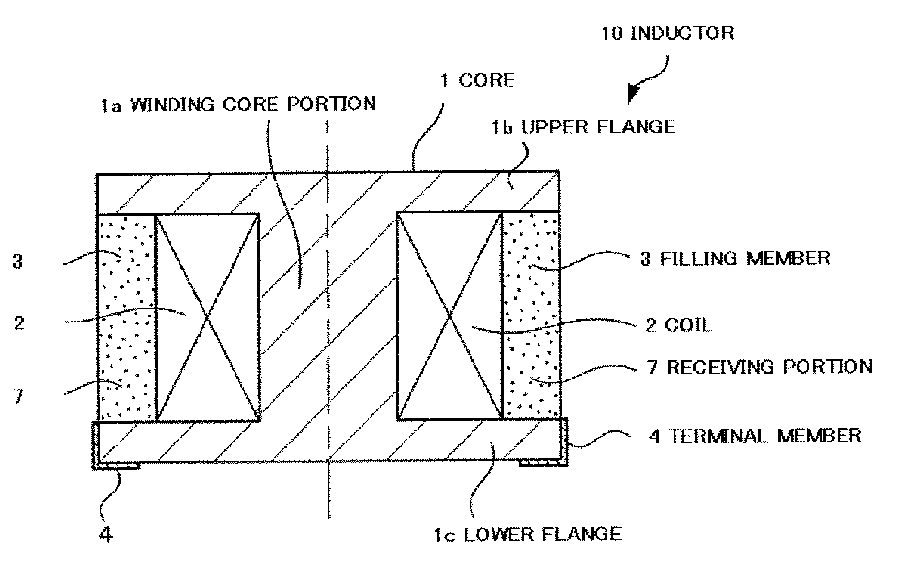
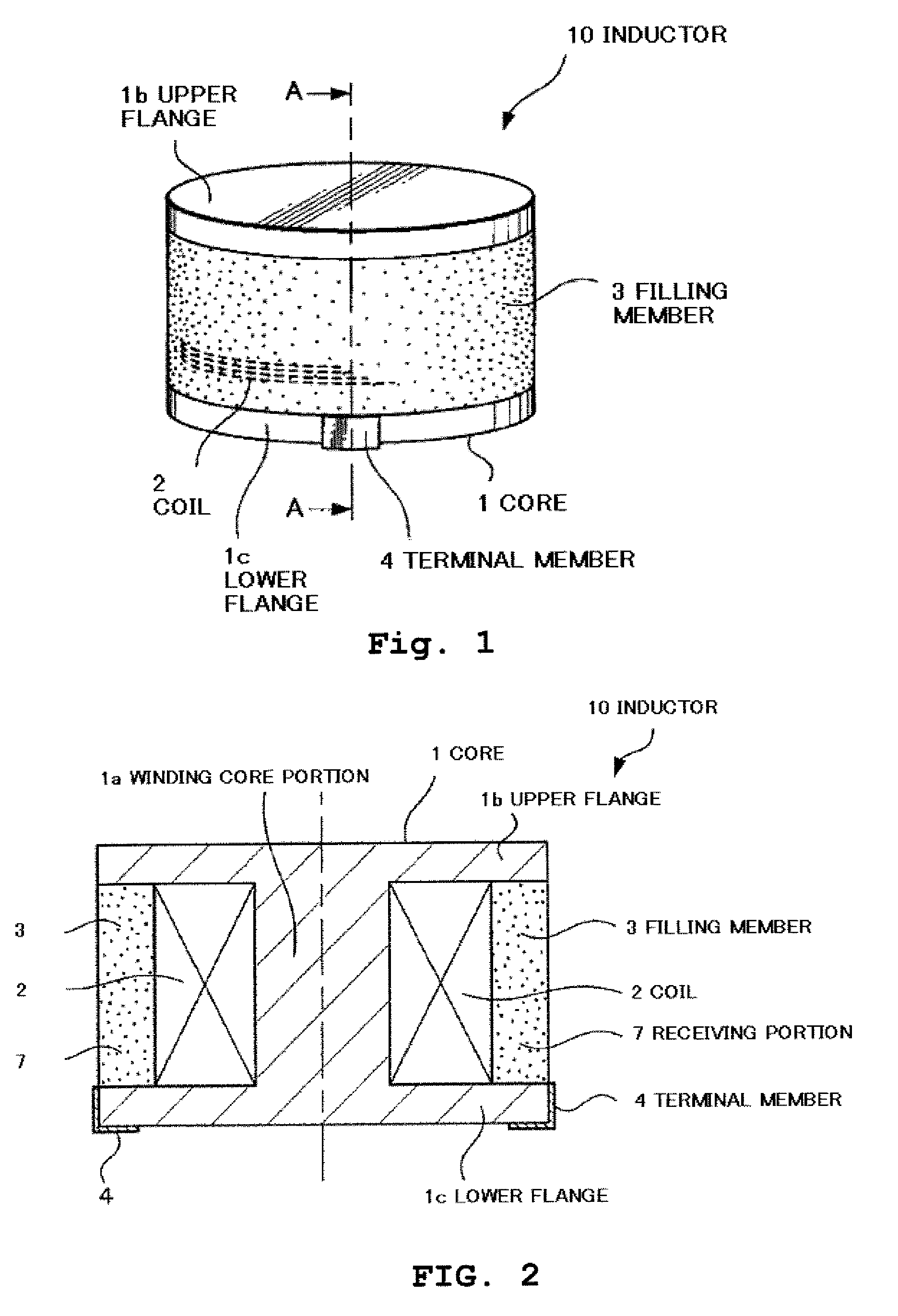
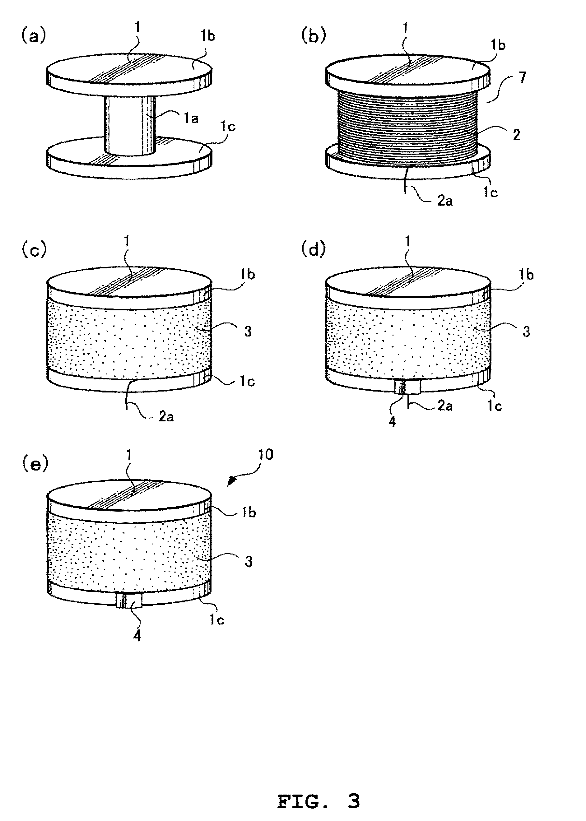
[0040]FIG. 1 is a perspective view of an inductor 10 relating to one exemplified embodiment of the present invention.

[0041]As shown in FIG. 1, the inductor 10 is constituted by a core 1, a coil 2 wound on the core 1, a filling member 3 coating the coil 2 and a connection terminal 4.

[0042]The core 1 is a drum type core constituted by an upper flange 1b, a lower flange 1c and a winding core portion 1a which is provided so as to link the upper flange 1b and the lower flange 1c.

[0043]The core 1 is molded by a compound material which is constituted by mixing a soft magnetic metal material of sendust or the like as a magnetic material and a thermo-setting resin of an epoxy resin or the like as a resin material. In addition, instead of the thermo-setting resin, it is also allowed to use a compound material constituted by mixing a thermoplastic resin of poly phenyle...

second exemplified embodiment

[0070]Next, it will be explained with respect to a second exemplified embodiment of a coil component of the present invention.

[0071]FIG. 6 is a perspective view of an inductor 20 relating to one exemplified embodiment of the present invention.

[0072]As shown in FIG. 6, the inductor 20 relating to this exemplified embodiment is constituted by a core 11, a coil 12 housed in the core 11, a filling member 13 coating the coil 12 and a connection terminal 14.

[0073]The core 11 is a pot type core constituted by a circular bottom face portion 11b, a periphery wall portion 11c linked along the periphery of the bottom face portion 11b and an axial core portion 11a provided at the center of the bottom face portion 11b. Also, at an upper end portion of the periphery wall portion 11c, there are formed wiring grooves 11d for pulling out coil end portions 12a of the coil 12 housed in the inside of the core 11 to the outside. It should be noted that the axial core portion 11a, the bottom face portion...

third exemplified embodiment

[0093]Next, it will be explained with respect to a third exemplified embodiment of a coil component of the present invention.

[0094]FIG. 9 is a perspective view of an inductor 30 relating to one exemplified embodiment of the present invention.

[0095]In FIG. 9, the same reference numerals are applied to portions corresponding to those in FIG. 6 and the explanation thereof will be omitted.

[0096]As shown in FIG. 9, the inductor 30 relating to this exemplified embodiment is constituted by a core 21 and a coil 12 which is housed in the core 21 and which is not shown in the drawing, a filling member 13 coating the coil 12 and a connection terminal 14.

[0097]The core 21 is a pot type core constituted by a circular bottom face portion 11b and a periphery wall portion 11c linked along the periphery of the bottom face portion 11b. Also, at the upper end portion of the periphery wall portion 11c, there are formed wiring grooves 11d for pulling out end portions 12a of the coil 12 housed in the ins...


PUM

PropertyMeasurementUnit
magneticaaaaaaaaaa
soft magneticaaaaaaaaaa
magnetic fluxaaaaaaaaaa

Abstract

In an inductor including a coil, a drum type core constituted by a soft magnetic metal material and a resin material, and a filling member constituted by a soft magnetic metal material and a resin material in which a magnetic flux excited by aforesaid coil goes through aforesaid drum type core and aforesaid filling member serially, the present invention constitutes an inductor, wherein aforesaid drum type core is constituted by injection molding so as to include a receiving portion, aforesaid coil is arranged in aforesaid receiving portion, and aforesaid filling member is filled therein.

Description

TECHNICAL FIELD[0001]The present invention relates to a coil component and a manufacturing method of the coil component, and more particularly, relates to a small-sized coil component used in an electronic apparatus and a manufacturing method of the coil component.BACKGROUND ART[0002]In recent years, along with miniaturization of an electronic apparatus, a request for miniaturization with respect to a coil component of an inductor or the like has been issued strongly. When forming an inductor in a small size, for example, thickness of a flange included in a core becomes thin and there will occur such a problem that strength of the inductor lowers.[0003]In order to solve this problem, there is known a technology in which a core forming a post shape is molded by using a compound member obtained by mixing a function material powder and a resin, whose strength is heighten than that of a sintered core composed of ferrite core or the like (for example, see Patent Document 1).[0004]Also, a...

Claims


Application Information

Patent Timeline
Patent Type & Authority Applications(United States)
IPC IPC(8): H01F17/04B29C45/14
CPCH01F1/14791H01F1/26H01F3/10H01F17/043H01F17/045Y10T29/4902H01F27/292H01F27/306H01F41/005H01F41/0246H01F2017/048H01F27/027H01F17/04H01F41/02
Inventor SAKAMOTO, SHINICHI
Owner SUMIDA CORP
Why Eureka
Try Eureka