Laser sensor system based on self-mixing interference

a laser sensor and interference technology, applied in the direction of reradiation, distance measurement, instruments, etc., can solve the problem of laser light modulation, achieve the effect of improving the signal-to-noise ratio of detected modulation, preventing non-linearities, and increasing the detection range of sensor modules

Active Publication Date: 2011-01-13
TRUMPF PHOTONIC COMPONENTS GMBH
View PDF13 Cites 45 Cited by
  • Summary
  • Abstract
  • Description
  • Claims
  • Application Information

AI Technical Summary

Benefits of technology

[0007]As an alternative to the classical interferometer approach the detector may detect a modulation of resonating laser light in the laser source. The modulation of the laser light in the laser source may be induced by laser light reflected by the target reentering the laser source. The effect is known as Self-Mixing-Interference (SMI) by those skilled in the art. Depending on the electrical driving scheme of the laser source either the distance and / or the velocity of the target can be detected. The detector may be a photo-diode and the laser source may be a laserdiode as for example a side emitting laser-diode a Vertical Cavity Surface Emitting Laser (VCSEL) or Vertical Extended Cavity Surface Emitting Laser (VECSEL). Especially VCSEL or VECSEL allow integrating the photodiode and the laser-diode in one device by means of semiconductor processing. Details about detection of velocities by means of self-mixing interference can for example be found in WO 02 / 37410 A1 FIG. 2 to FIG. 7 and the related description.
[0008]In another embodiment according to the current invention the control element comprises an optical element and the optical element is placed between the target and the laser source. The intensity of the laser light may for example be varied by means of a variable optical attenuator between the laser source and the target, which may improve signal to noises ratio of the detected modulation of the laser light by preventing non-linearities caused by high intensities of the laser light reflected by the target. Alternatively or in addition the focus point of the laser light may be varied by means of a variable focus lens, which may increase the detection range of the sensor module in comparison to sensor modules with a lens with a fixed focus. Further the laser light may be slanted with respect to a reference axis by means of a moveable mirror between the laser source and the target, which may increase the range of velocities those may be detected as discussed above in connection with the slanting of the laser source itself.
[0009]In a further embodiment according to the current invention the sensor module comprises at least two laser sources and at least two detectors and the laser sources are adapted to emit laser light in essentially the same direction. The adaption of the laser sources to emit laser light in essentially the same direction means that the laser sources are aligned in parallel in order to emit laser light in the same direction. After the emission the laser light emitted by the different laser sources may be manipulated e.g. by means of the control element causing a deviation from the direction of emission of the laser light, whereby the deviation from the direction of emission of the laser light may be different for different laser sources. Each laser source may have a dedicated detector only detecting the modulation of the laser light emitted by the belonging laser source. The laser sources and the detectors may for example be integrated SMI sensors manufactured by semiconductor processing. The laser light of at least two different laser sources may be varied differently by means of the control element with respect to the focus point of the laser light and / or the intensity of the laser light and / or the direction of the laser light. The latter may be done for example by means of variable optical attenuators, variable focus lenses or moveable mirrors provided for at least two or all laser sources integrated in the sensor module. Alternatively a passive optical element may be used in order to vary or manipulate the laser light emitted by the laser sources differently. This may for example be done by means of a curved mirror reflecting laser light emitted by one laser source depending on the point on the mirror where the emitted laser light hits the mirror. Using an array of laser sources and detectors may enable a variation of the slanting angle with respect to a reference axis without moving parts. Further lenses with different focal length may be used in order to vary the focus points of laser sources in an array of laser sources. Alternatively or in combination with lenses and / or mirrors the passive optical element may be an optical attenuator. Using for example a first optical attenuator with a first optical attenuation in combination with a first laser source and a first detector and a second optical attenuator with a second optical attenuation different from the first optical attenuation in combination with a second laser source and a second detector may simplify the sensor module. The different laser sources may be driven in parallel or the laser sources may be driven sequentially by using an appropriate electrical driving circuit. Driving the different laser sources sequentially (one after the other) may reduce the complexity of the electronic circuitry. Using passive optical elements in combination with an array of laser sources and detectors (three, four, five or more laser sources and detectors) may enable a flexible, cost effective and reliable sensor module.

Problems solved by technology

The modulation of the laser light may be caused by a Doppler shift of reflected laser light due to the movement of the target interfering with the laser light emitted by the laser source.

Method used


Image

  • Laser sensor system based on self-mixing interference
  • Laser sensor system based on self-mixing interference
  • Laser sensor system based on self-mixing interference

Examples


first embodiment

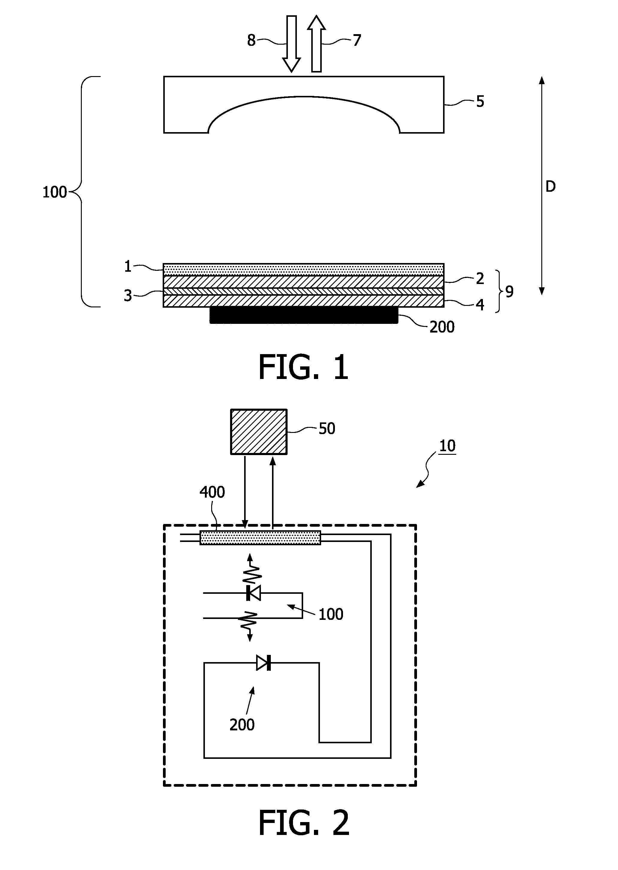
[0035]FIG. 2 shows a schematic view of a sensor module 10 according to the current invention. A laser source 100 in this case a VCSEL is connected to a driving circuit (not shown) and a power source (not shown). The laser light emitted by the VCSEL passes a control element 400 comprising a lens with variable focus and control circuitry both being also connected to the power source (not shown). After passing the lens with variable focus the laser light hits the target 50 and a part of the laser light is reflected by the target 50, passes the autofocus lens again and reentes the laser cavity of the VCSEL causing a modulation of the laser light in the laser cavity. The modulation of the laser light in the laser cavity is detected by a detector 200 being a photodiode attached to the VCSEL as discussed above. The electrical signal being generated by means of the photodiode due to the modulation of the laser light in the laser cavity comprises the information to determine e.g. the velocit...

second embodiment

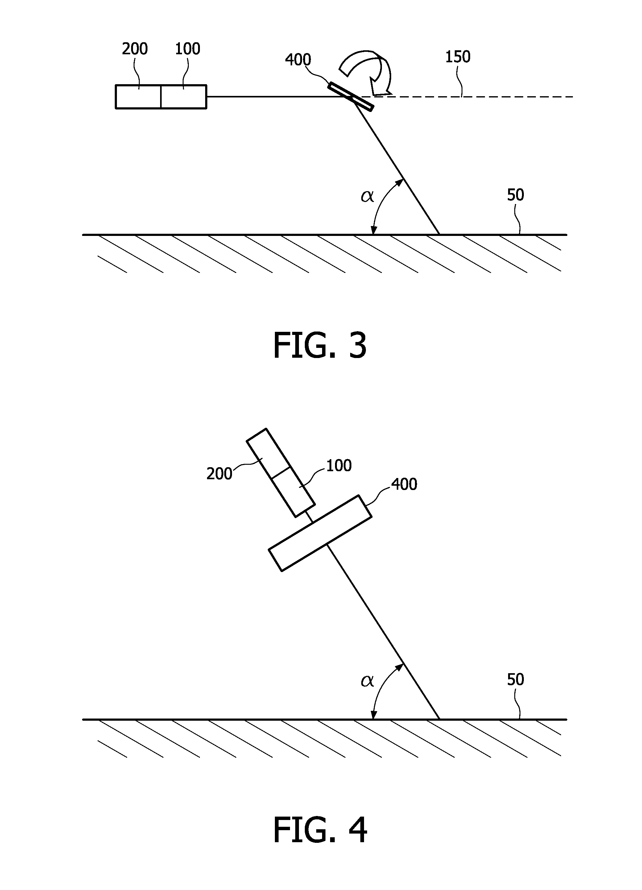
[0036]A schematic view of a sensor module according to the current invention is depicted in FIG. 3. The laser source 100 being attached to a detector 200 emitts laser light that may be focused by means of a lens (not shown). The laser light emitted by the laser source 100 hits the control element 400, whereby the control element 400 comprises a controllable mirror, control circuitry (not shown) and a motor (not shown) to slant the mirror as indicated by the arrow in FIG. 3 with respect to the reference axis 150 defined by the laser light emitted by the laser source 100 before hitting the controllable mirror. Depending on the slanting angle of the controllable mirror with respect to the reference axis 150 the angle of incident a between the laser light deflected by the controllable mirror and the surface of the target 50 changes. The deflected laser light is at least partly reflected by means of the target 50, again deflected by the controllable mirror and reenters the laser cavity o...

third embodiment

[0037]In FIG. 4 a schematic view of a sensor module according to the current invention is shown. The laser source 100 being attached to a detector 200 emits laser light that may be focused by means of a lens (not shown). The laser light emitted by the laser source 100 hits the control element 400, whereby the control element 400 comprises a controllable optical attenuator and control circuitry (not shown). The laser light is at least partly reflected by means of a target 50, passes again the controllable optical attenuator and reenters the laser cavity of the laser source 100 causing a modulation of the laser light in the laser cavity being detected by the detector 200. A computing unit (not shown) may be connected to the detector 200 evaluating the electronic signal provided by the detector 200. The controllable optical attenuator may be used to optimize the signal to noise ratio of the sensor module by controlling the amount of laser light reentering the laser cavity. The control ...


PUM


Abstract

A sensor module (1) for measuring the distance to a target and/or the velocity of the target (50), the sensor module (1) comprising at least one laser source (100), at least one detector (200) being adapted to detect modulated laser light and at least one control element the control element (400) being adapted to vary the focus point of the laser light and/or the intensity of the laser light and/or the direction of the laser light. The control of the laser light emitted by the laser source (100) either by active optical devices as variable focus lenses or controllable attenuators or passive optical elements in combination with arrays of laser sources (100) and detectors (200) enable flexible and robust sensor modules.

Description

FIELD OF THE INVENTION[0001]The current invention is related to a system and a method for measuring the distance to a target and / or the velocity of the target. The invention is further related to the use of such a system.BACKGROUND OF THE INVENTION[0002]In US 2007 / 0058157 A1 a system for measuring velocity of a target is disclosed. The system includes a laser device, a detector and a signal processor. The laser device produces a frequency-modulated laser beam, wherein the frequency-modulated beam is split into at least two laser beams, wherein a reflected beam comprising one split beam is directed to the target and reflected from the target. The detector detects a combination of the reflected beam and a reference beam comprising another split beam, wherein the reflected beam and the reference beam have unequal delays. The signal processor obtains velocity information from the combined beam by use of Doppler-shifted harmonics of the modulation frequency. Dynamic range and flexibility...

Claims


Application Information

Patent Timeline
Patent Type & Authority Applications(United States)
IPC IPC(8): G01C3/00
CPCG01P3/366G01S7/4916G01S17/58G01S7/4811
Inventor MOENCH, HOLGERCARPAIJ, MARKVAN DER LEE, ALEXANDER M.SCHWAN, STEFANHAN, MENGSCHEMMANN, MARCEL F.C.
Owner TRUMPF PHOTONIC COMPONENTS GMBH
Why Eureka
Try Eureka