Feed Delivery System For A Solid-Liquid Separation Vessel

a separation vessel and feed technology, applied in the separation process, working-up pitch/asphalt/bitumen, liquid displacement, etc., can solve the problems of hindering the ability of fine particles to escape, and achieve the effect of minimizing dispersion, facilitating separation of fine particles, and facilitating escap

Inactive Publication Date: 2011-01-20
EXXONMOBIL UPSTREAM RES CO
View PDF63 Cites 20 Cited by
  • Summary
  • Abstract
  • Description
  • Claims
  • Application Information

AI Technical Summary

Benefits of technology

[0004]Consistent with an aspect of the instant invention, a very different feed delivery system is required in those applications where it is important to separate a significant fraction of the fine particles having terminal velocities much smaller that the superficial upward velocity. In this case, a specialized feed delivery system is required to enhance the separation of fine particles with low terminal velocities. Rather than distributing the feed over a wide-cross section of the vessel, which simply leads to a high carry-over rate of fine particles, the novel approach embodied by aspects of the instant invention seeks to limit the horizontal distribution of the feed, seeking instead to minimize dispersion and trap the smaller particles either between the larger particles or in the hydrodynamic wakes of the larger particles. Thus, the smaller particles may be dragged down by the larger particles. Maintaining a high particle concentration within the inflow stream, combined with a low momentum flux, hinders the ability of fine particles to escape. The effectiveness of this approach is further enhanced by exploiting buoyancy forces which act on the inflowing slurry stream, causing it plunge aggressively upon entering the vessel, carrying the particles into the lower cone where densification occurs, with fine particles remaining entrapped within the high concentration of larger particles.

Problems solved by technology

Maintaining a high particle concentration within the inflow stream, combined with a low momentum flux, hinders the ability of fine particles to escape.

Method used


Image

  • Feed Delivery System For A Solid-Liquid Separation Vessel
  • Feed Delivery System For A Solid-Liquid Separation Vessel
  • Feed Delivery System For A Solid-Liquid Separation Vessel

Examples


Embodiment Construction

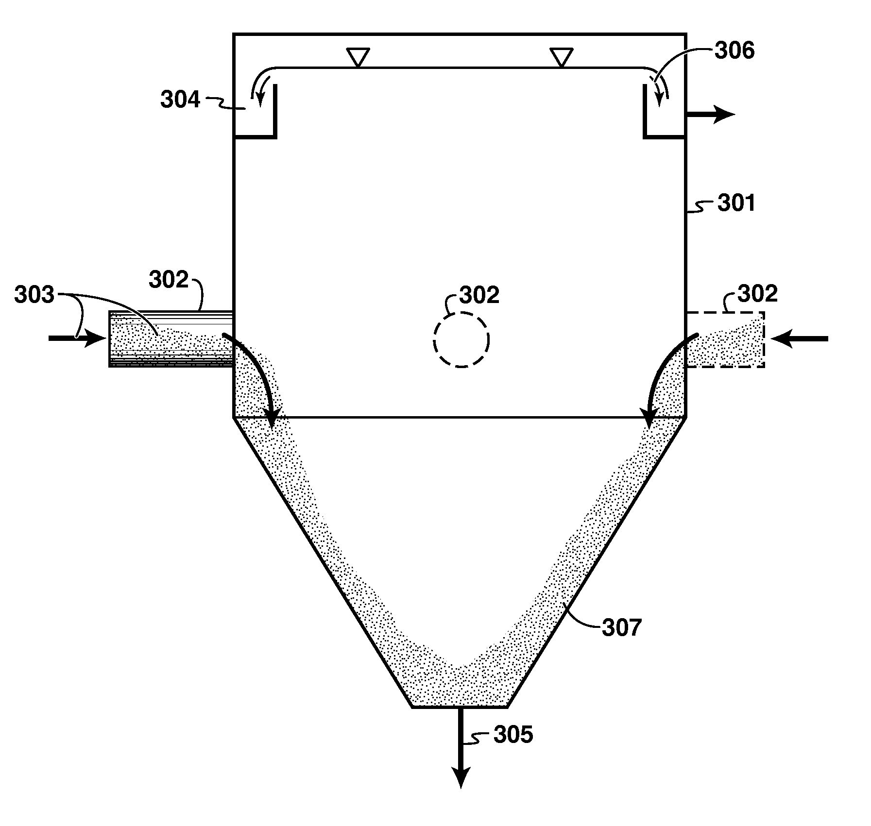
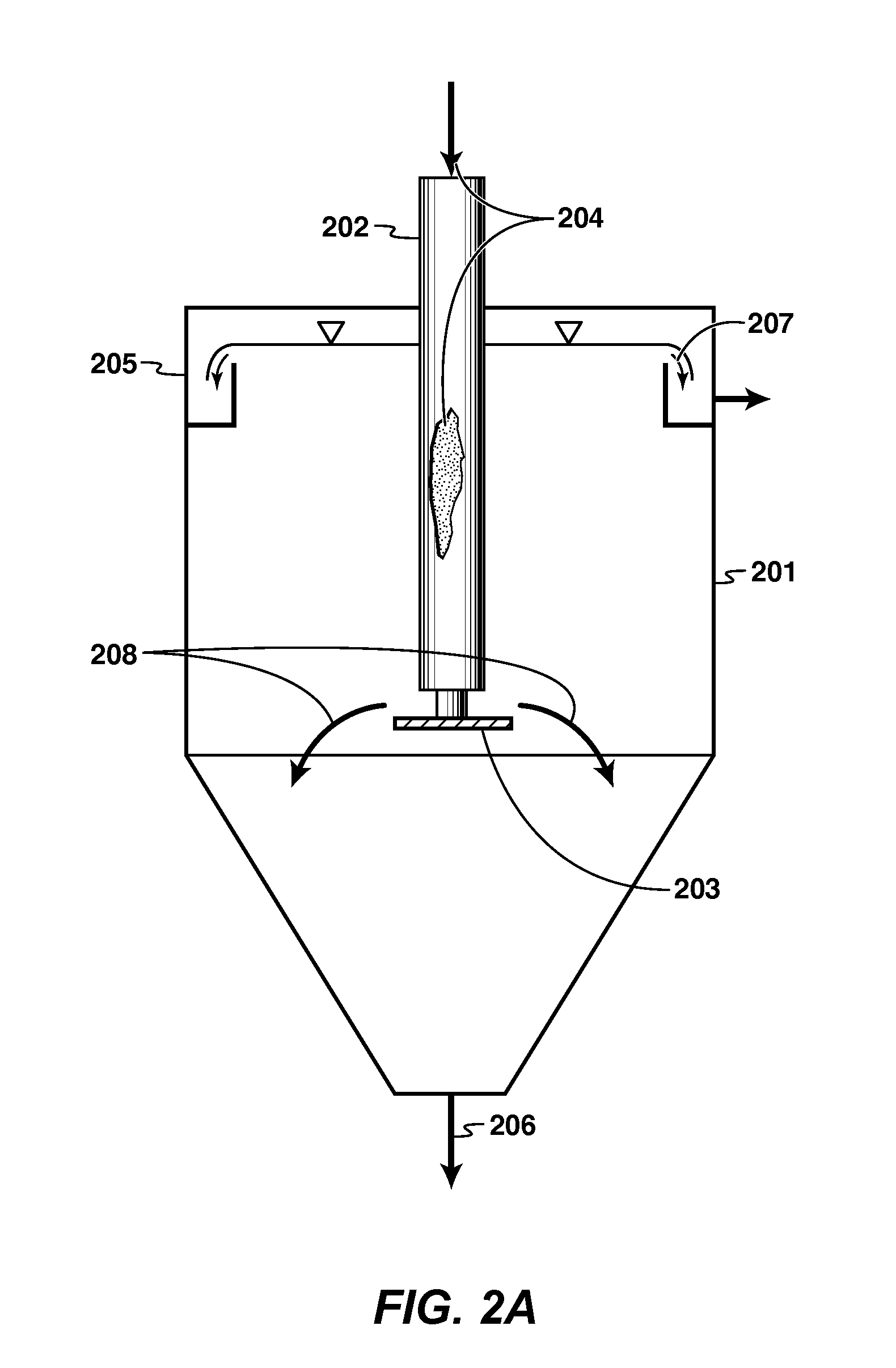
[0023]Myriad solid-liquid separation vessels such as gravity, filtration, etc. are known. Gravity separation can be further classified according to the magnitude of the gravity force involved in the separation. For example, a 1 G force separator is typically called a thickener / clarifier and cyclones and centrifuges are typical high G force separators. A typical thickener type of separator is characterized by a cylindrical upper section with a conical lower section to withdraw settled / separated solids from the process.

[0024]One class of separation vessels to which the instant feed delivery may be applied are gravity separation vessels. One sub-class of gravity separation vessels to which the instant feed delivery may be applied are froth separation units (FSUs) used to separate tailings and diluted bitumen from a bitumen froth feed. FSUs will be now be explained further.

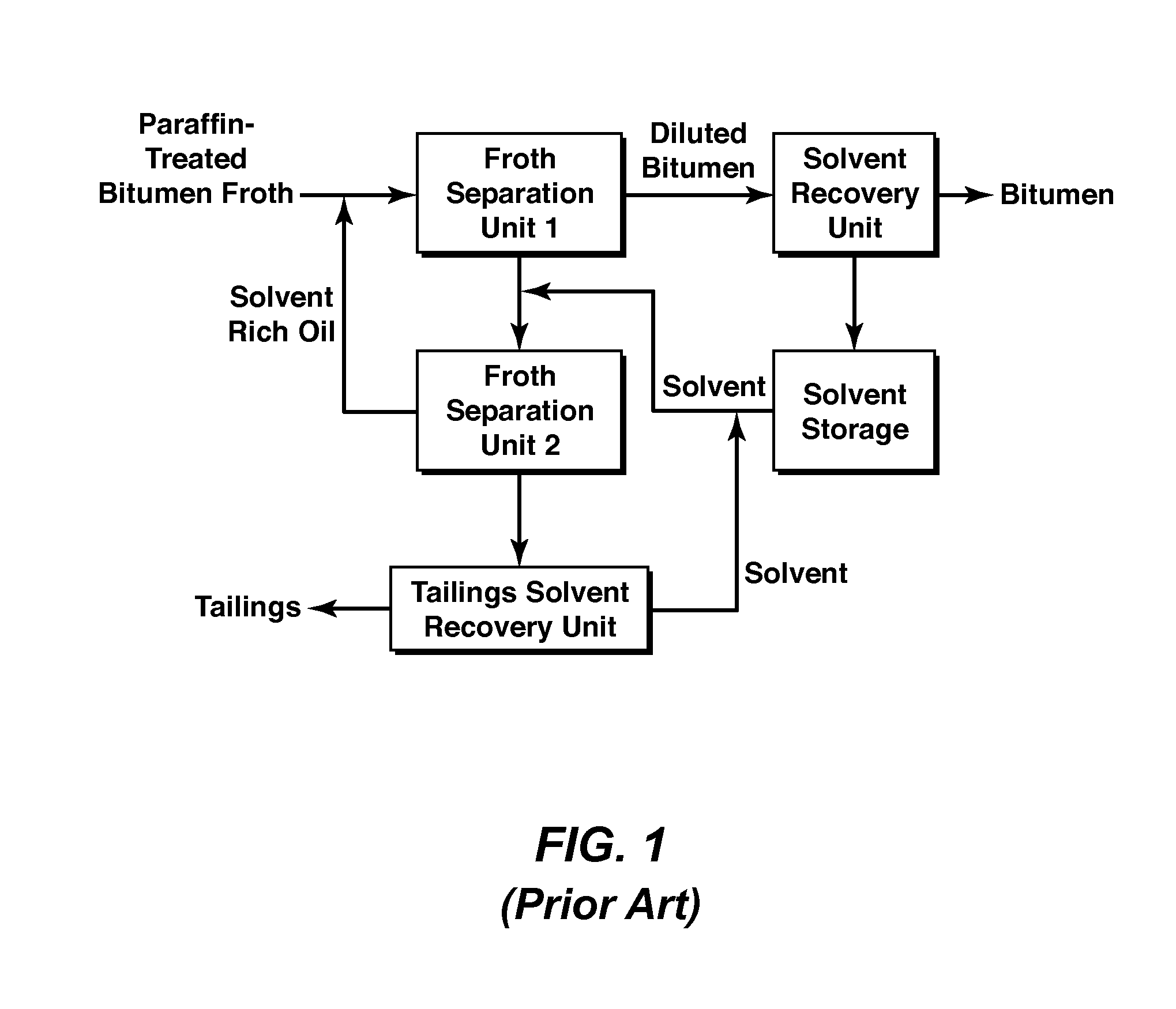
[0025]Among several processes for bitumen or heavy oil extraction, the Clark Hot Water Extraction (CHWE) process re...


PUM

PropertyMeasurementUnit
temperatureaaaaaaaaaa
operating pressuresaaaaaaaaaa

Abstract

A method of delivering feed, for example a paraffinic solvent treated bitumen froth, to a separation vessel, for example a froth separation unit (FSU). The feed is delivered from one or more side inlets that may be substantially normal to, and flush with, the wall of the vessel. In contrast to certain conventional feed systems used in gravity separators which use a distributor plate to widely distribute the feed with a vessel, the feed is delivered such that it flows down the inside wall of the vessel. This feed delivery is characterized by a Richardson number of greater than 1.0. Such feed delivery is particularly useful where the feed has particles with a bi-modal size distribution to be separated from an overflow stream. The gentle flow serves to mitigate the upward flux of the smaller particles, for example mineral solids, by being trapped below the larger particles, for example precipitated asphaltene aggregates.

Description

CROSS-REFERENCE TO RELATED APPLICATION[0001]This application claims priority from Canadian Patent Application 2,672,004 filed Jul. 14, 2009 entitled FEED DELIVERY SYSTEM FOR A SOLID-LIQUID SEPARATION VESSEL, the entirety of which is incorporated by reference herein.FIELD OF THE INVENTION[0002]This invention is in the field of solid-liquid gravity driven separation vessels. More particularly, this invention relates to the feed delivery system used in a solid-liquid gravity driven separation vessel.BACKGROUND OF THE INVENTION[0003]Many industrial processes require solid particles to be separated from a continuous liquid phase. In gravity separators, a slurry stream comprising liquid and solid particles is delivered to a vessel where the solid particles settle by gravity and are removed from the bottom of the vessel, while the clarified liquid is removed from the top of the vessel. In most processes, the solid particles are distributed in size, where the large particles settle more qui...

Claims


Application Information

Patent Timeline
Patent Type & Authority Applications(United States)
IPC IPC(8): B01D21/24B03B9/00B01D17/04C10G33/06C10C3/08
CPCC10G1/045C10G2300/1033C10G2300/805B01D21/2405B03D1/247B03D1/1412B03D1/1456B03D1/1493Y10T137/8593
Inventor SUTTON, CLAY R.SURY, KEN N.KIEL, DARWIN EDWARDDIEP, JOHN KHAI-QUANG
Owner EXXONMOBIL UPSTREAM RES CO
Why Eureka
Try Eureka