Electric power converter

Active Publication Date: 2011-01-20
FUJI ELECTRIC CO LTD
View PDF5 Cites 48 Cited by
  • Summary
  • Abstract
  • Description
  • Claims
  • Application Information

AI Technical Summary

Benefits of technology

[0028]According to the invention, there can be obtained advantages that high efficiency operations of an electric power converting unit and a load become possible and, along with this, a normal operation of a load can be ensured even in the case when abnormalities occur in constituents such as a battery unit in a battery, a DC link capacitor in a DC

Problems solved by technology

This increases a switching loss of the switching device (an IGBT and a diode) and, along with this, also on the side of the AC motor 107, increases a ripple in a flowing current to increase a harmonic loss due to carrier frequency components, which results in a decrease in efficiency of the AC motor to be an unsolved problem.
However, the DC to AC converting circuit 106 with a configuration normally provided with the three-level circuit causes controls of the twelve switching devices forming the DC to AC converting circuit 106 to be complicated to increase the load on the control circuit controlling the DC to AC converting circuit 106, which becomes a new problem.
Thus, when only any one unit causes failure for some reason, the battery units connected in series causes the whole of the battery s

Method used


Image

  • Electric power converter
  • Electric power converter
  • Electric power converter

Examples


first embodiment

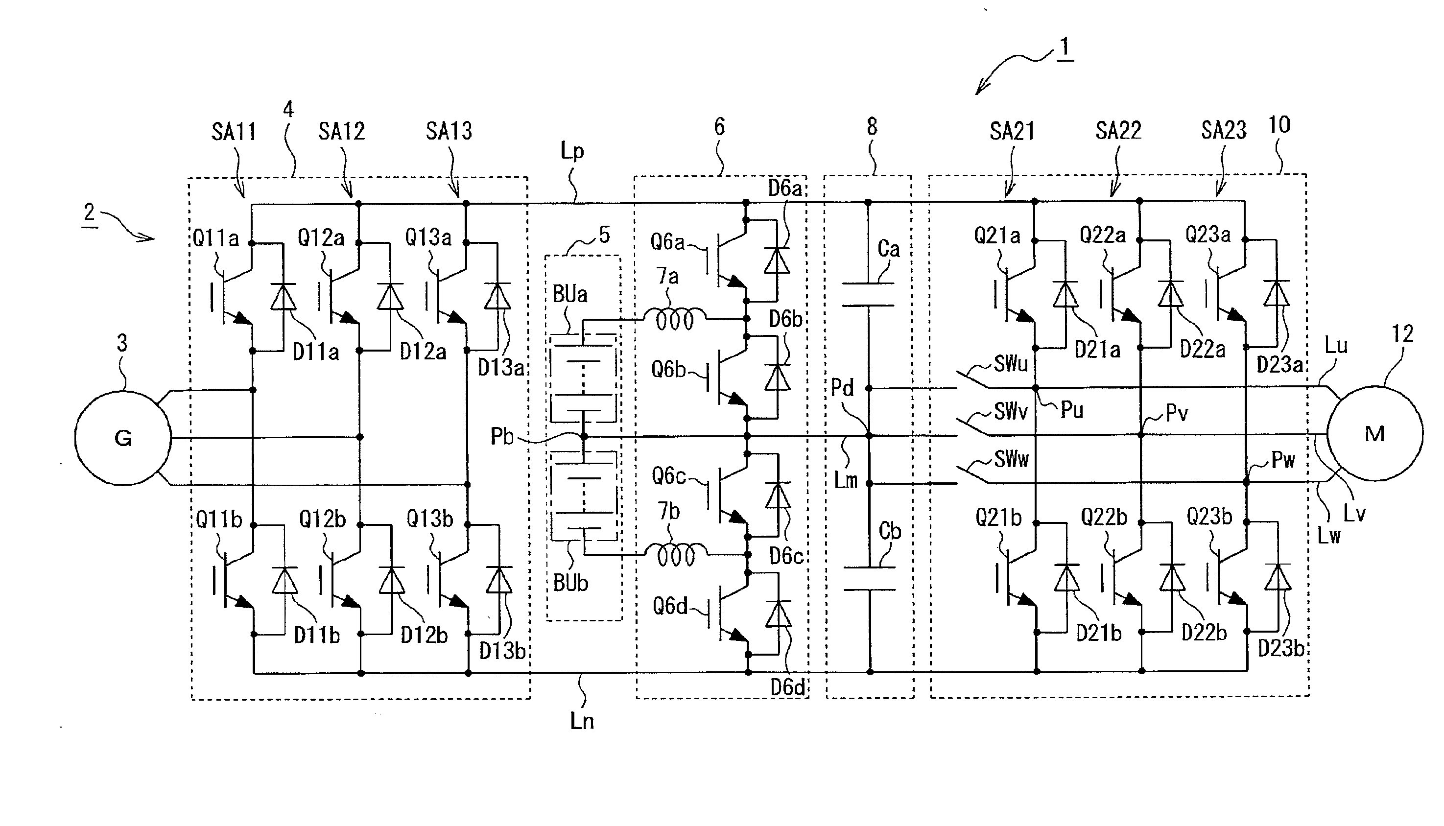
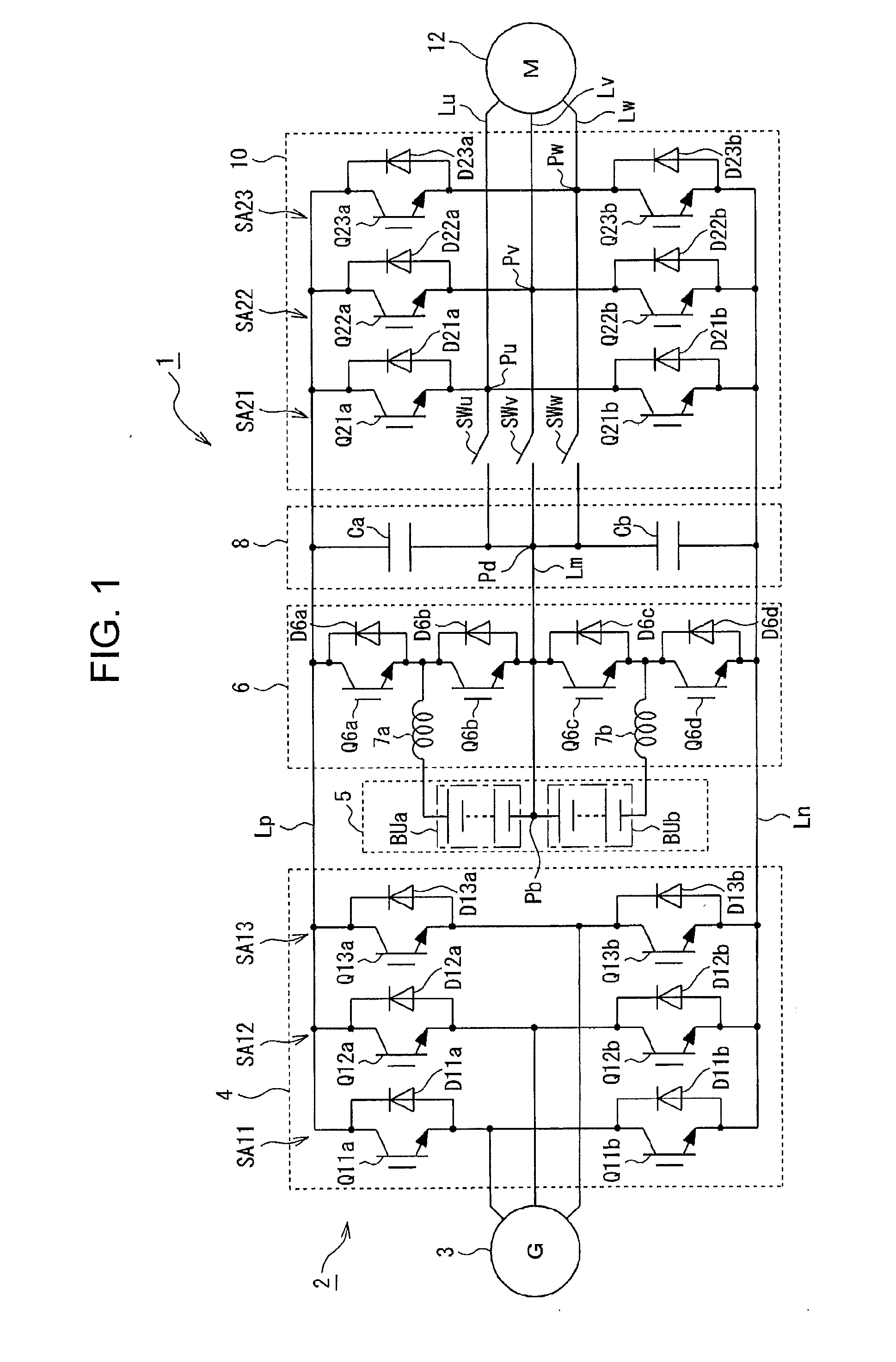
[0056]FIG. 1 is a block diagram showing a circuit configuration of an electric converter according to the invention. In FIG. 1, reference numeral 1 denotes an electric power converter applied to a hybrid electric vehicle. The electric power converter 1 has a DC power supply section 2 that outputs DC electric power by electric power generation. The DC power supply section 2 is provided with an AC generator 3 coupled to an output shaft of an internal combustion engine such as an auto engine and an AC to DC converter section 4 formed with an AC to DC converter circuit that converts three-phase AC electric power outputted from the AC generator 3 to DC electric power.

[0057]The AC to DC converter section 4 has three switching arms SA11 to SA13 connected in parallel to one another between a positive electrode side line Lp and a negative electrode side line Ln. The switching arms SA11 to SA13 have their respective pairs of switching devices Qia and Qib (i=11 to 13) each being formed with, f...

second embodiment

[0127]In the next, a second embodiment according to the invention will be explained with reference to FIG. 19 to FIG. 23.

[0128]FIG. 19 is a block diagram showing a circuit configuration of a second embodiment of the electric power converter according to the invention, FIG. 20 is a block diagram showing the second embodiment of the electric power converter according to the invention with a control unit included, FIG. 21 is a block diagram showing a specific configuration of the control unit shown in FIG. 20, FIG. 22 is a diagram illustrating an operation in an abnormal state of a DC link capacitor in the DC circuit in the second embodiment and FIG. 23 is a diagram illustrating an operation in an abnormal state of a battery unit in the second embodiment.

[0129]In the second embodiment, even in the case when an abnormality occurs in the battery unit BUa or BUb in the battery 5 or in the case when an abnormality occurs in one of the DC link capacitors Ca and Cb in the DC circuit 8, the A...

third embodiment

[0145]In the next, a third embodiment according to the invention will be explained with reference to FIG. 24.

[0146]FIG. 24 is a block diagram showing a circuit configuration of a third embodiment of the electric power converter according to the invention.

[0147]The third embodiment has the same configuration as that of the first embodiment shown in FIG. 1 explained before except that the voltage step-up section in each of the first and second embodiments is simplified so that the positive electrode side of the battery 5 is connected through a step-up reactor 7 to the connection point of switching devices Q6e and Q6f connected in series between the positive electrode side line Lp and the negative electrode side line Ln. Thus, the parts corresponding to those shown in FIG. 1 and FIG. 19 are denoted by the same reference numerals and signs with detailed explanations thereof being omitted. To the switching devices Q6e and Q6f, diodes D6e and Df6 are connected, respectively, in inverse pa...


PUM


Abstract

An electric power converter includes a DC to DC converter section adjusting DC power of a battery with at least two units in series, a DC circuit having at least two DC link capacitors in series between a positive and a negative line from the DC to DC converter section, an electric power converter section connected to the DC circuit to convert DC electric power to AC electric power for a motor, a bilateral switching circuit connecting an intermediate potential point between the capacitors and an AC output point in the electric power converter section, and a short-circuit between the intermediate potential point of the DC circuit and an intermediate potential point between the battery units. Normal operation of a load is ensured even when the battery, the capacitor in the DC circuit or the switching device in the electric power converter section becomes abnormal, while achieving high efficiency.

Description

1. FIELD OF THE INVENTION[0001]The present invention relates to an electric power converter which can be applied to a device such as a hybrid electric vehicle or an electric vehicle that drives a motor by electric power supplied from at least a battery.2. BACKGROUND ART[0002]For an electric power converter of a equipment represented by a hybrid electric vehicle, a converter, for example, is known which has a configuration given in FIG. 25, a block diagram sowing a circuit configuration of a related power converter. More specifically, the electric converter has a configuration including a DC power supply unit 102, a DC to DC converting circuit 104, a DC circuit 105 and a DC to AC converting circuit 106. The DC power supply unit 102 is formed with an AC to DC converting circuit converting three-phase AC electric power generated by an AC generator 101 to DC electric power. The DC to DC converting circuit 104 raises the DC voltage of a battery 103 connected between a positive electrode ...

Claims


Application Information

Patent Timeline
IPC IPC(8): H02P27/00B60L50/15
CPCB60L3/003B60L3/0046B60L2210/10B60L2210/20Y02T10/725H02P27/06Y02T10/642Y02T10/7216H02M7/483B60L58/18Y02T10/64Y02T10/72Y02T10/70
Inventor TAKIZAWA, SATOKIGEKINOZU, MASAKAZU
Owner FUJI ELECTRIC CO LTD
Why Eureka
Try Eureka