However, there are inherent resolution limitations, with existing devices typically providing no more than 2148×1080 pixels.
In addition, high component and system costs have limited the suitability of DLP designs for higher-quality digital cinema projection.
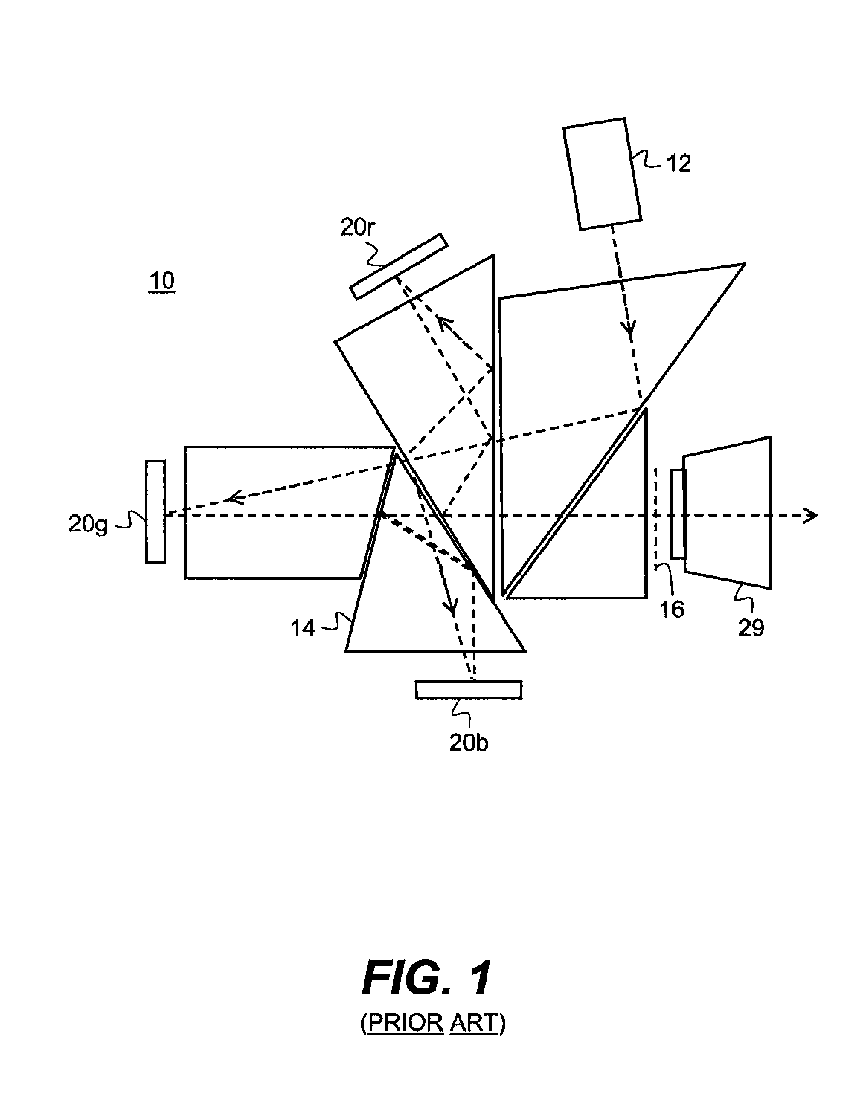
Moreover, the cost, size, weight, and complexity of the Philips
prism or other suitable combining prisms are significant constraints.
In addition, the need for a relatively fast
projection lens with a long working distance, due to brightness requirements, negatively impacts the acceptability and
usability of these devices.
However, with LCD components it can be difficult to maintain the high quality demands of digital cinema, particularly with regard to color and contrast, since the high
thermal load of high brightness projection affects polarization qualities of these devices.
There are also disadvantages, however.
The needed glasses are expensive.
Additionally, adjustment of the
color space can be difficult and there can be significant light loss due to filtering.
Although this arrangement offers efficient use of light, it can be an expensive configuration.
The
polarizer is required, since the DLP is not inherently designed to maintain the polarization of the input light, which is generally unpolarized, as the window of the device
package depolarizes due to
stress induced birefringence.
The glasses, however, add expense over embodiments that simply use a
polarizer.
With such MEMS-based systems, there can be significant light loss, resulting from the requirement to use polarized light, which can reduce output light by half over conventional non-stereoscopic designs.
There is additional cost due to the large polarization switcher as well as the alignment features and mounting to the front of the projections system.
The polarization switcher design is also more complicated in that it must essentially
handle the entire visible spectral band, retarding the light in equal amounts regardless of the
wavelength.
Failure to properly achieve this performance can generate unacceptable
crosstalk, directing images to the wrong eye and reducing the quality of the stereoscopic effect.
This type of
crosstalk effect can even be physically disturbing to the viewer, in some cases.
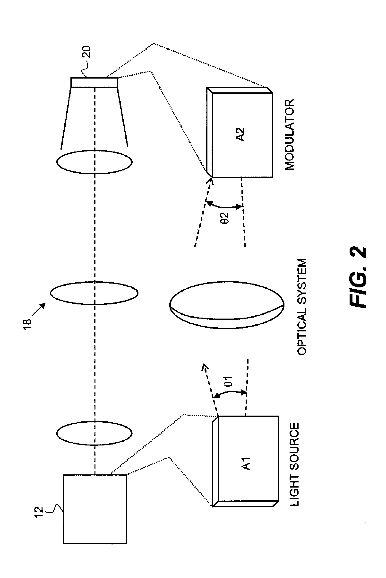
A continuing problem with illumination efficiency relates to etendue or, similarly, to the Lagrange invariant.
Similarly, increasing the
source image size, so that light originates over a larger area, increases etendue.
Larger image sizes, however, typically result in a more costly system.
This is especially true of devices such as LCOS and DLP components, where the
silicon substrate and defect potential increase with size.
As a general rule, increased etendue results in a more complex and costly optical design.
Moreover, although a configuration such as that disclosed in the '437 Sprotbery et al. disclosure handles light from three times the area of the final multicolor image formed, this configuration does not afford any benefit of increased brightness, since each color path contains only one-third of the total
light level.
Poorly matched etendue means that the optical system is either light-starved, unable to provide sufficient light to the spatial light modulators, or inefficient, effectively discarding a substantial portion of the light that is generated for modulation.
LCD-based systems have been compromised by the requirement for polarized light, reducing efficiency and increasing etendue, even where polarization
recovery techniques are used.
DLP device designs, not requiring polarized light, have proven to be somewhat more efficient, but still require expensive, short lived lamps and costly optical engines, making them too expensive to compete against conventional cinema projection equipment.
Projection apparatus that meet these requirements typically cost in excess of $50,000 each and utilize high wattage
Xenon arc lamps that need replacement at intervals between 500-2000 hours, with typical replacement cost often exceeding $1000.
The large etendue of the
Xenon lamp has considerable
impact on cost and complexity, since it necessitates relatively fast
optics to collect and project light from these sources.
One drawback common to both DLP and LCOS LCD spatial light modulators (SLM) has been their limited ability to use
solid-state light sources, particularly
laser sources.
Solid-state lasers promise improvements in etendue,
longevity, and overall spectral and brightness stability but, until recently, have not been able to deliver visible light at sufficient levels and at costs acceptable for digital cinema.
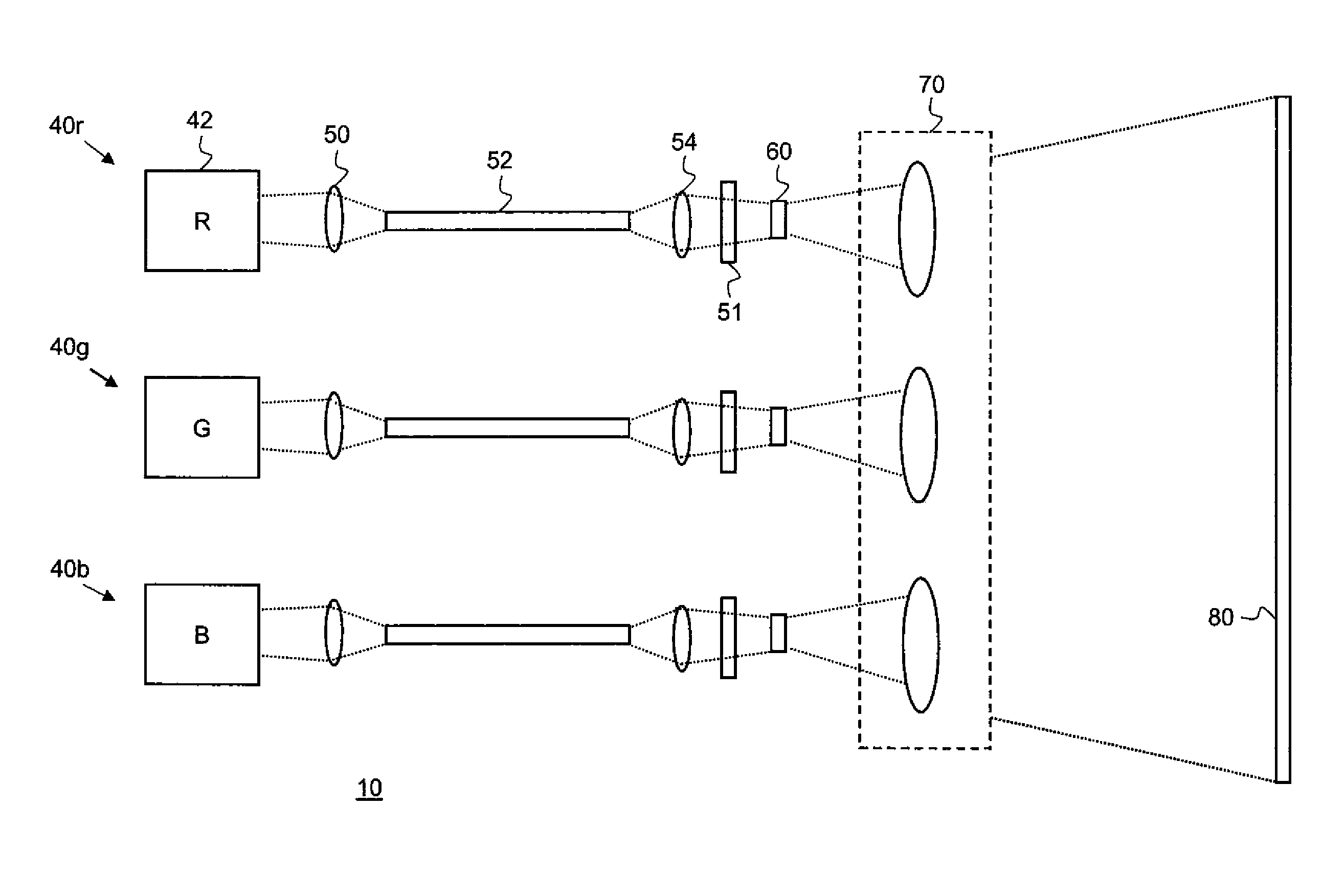
However, brightness itself is not yet high enough; the combined light from as many as nine individual arrays can be needed in order to provide the necessary brightness for each color.
However, conventional solutions using these devices have been prone to a number of problems.
One limitation relates to device yields.
Due largely to heat and packaging problems for critical components, the commercialized VECSEL array is extended in length, but limited in height; typically, a VECSEL array has only two rows of emitting components.
The use of more than two rows tends to increase yield difficulties dramatically.
In addition, conventional VECSEL designs are prone to difficulties with power connection and heat sinking.
Thus, there can be significant current requirements and
heat load from the unused current.
However, these are more difficult to
package in array form and traditionally have a shorter lifetime at higher brightness levels.
As noted earlier, increased etendue results in a more complex and more costly optical design.
Thus, it can be seen that the challenge of providing a stereoscopic color
projection system having cinema or near-cinema performance and brightness has not been met using conventional approaches.


