Fluid valve arrangement

a technology of valve arrangement and flow valve, which is applied in the direction of fluid dynamics, operating means/release devices of valves, servomotors, etc., can solve the problems of insufficient energy-saving operation of the arrangement, the arrangement is dependent on the function of the arrangement, and the difficulty in achieving accurate control of the consumer with this valve arrangement, so as to achieve the effect of minimizing the pressure loss in the system

Inactive Publication Date: 2011-01-27
PARKER HANNIFIN AB
View PDF39 Cites 42 Cited by
  • Summary
  • Abstract
  • Description
  • Claims
  • Application Information

AI Technical Summary

Benefits of technology

[0039]Using the information containing the data relating to the position of the constant pressure valves it is possible to determine not only the operating mode, but also the pressure required for controlling the load on the system. As described above, this prevents the fluid consumer from being connected to the supply connection when the supplied pressure is insufficient for driving the fluid consumer.
[0040]The constant pressure valve may comprise a spool valve and the opening degree sensor is a position sensor, which determines a position of a spool in said spool valve. In this way the pressure in the conduits on either side of each valve arrangement may act on either end of a spool valve that is pre-loaded by a spring means towards a neutral, central position. When the pressure drop across the pressure compensated valve becomes greater than the corresponding pre-load of a coil spring, or a similar spring means, the constant pressure valve will begin to throttle the flow in order to maintain a constant pressure drop across the pressure compensated valve. This constant pressure drop is about equal to the preload on the spring. The valve arrangement allows fo

Problems solved by technology

However, it is difficult to achieve an accurate control of the consumer with this valve arrangement, as friction in the mechanical parts, hysteresis in the solenoid valves and external forces, for example forces originating from the flow, prevent an exact positioning of the

Method used


Image

  • Fluid valve arrangement
  • Fluid valve arrangement
  • Fluid valve arrangement

Examples


Embodiment Construction

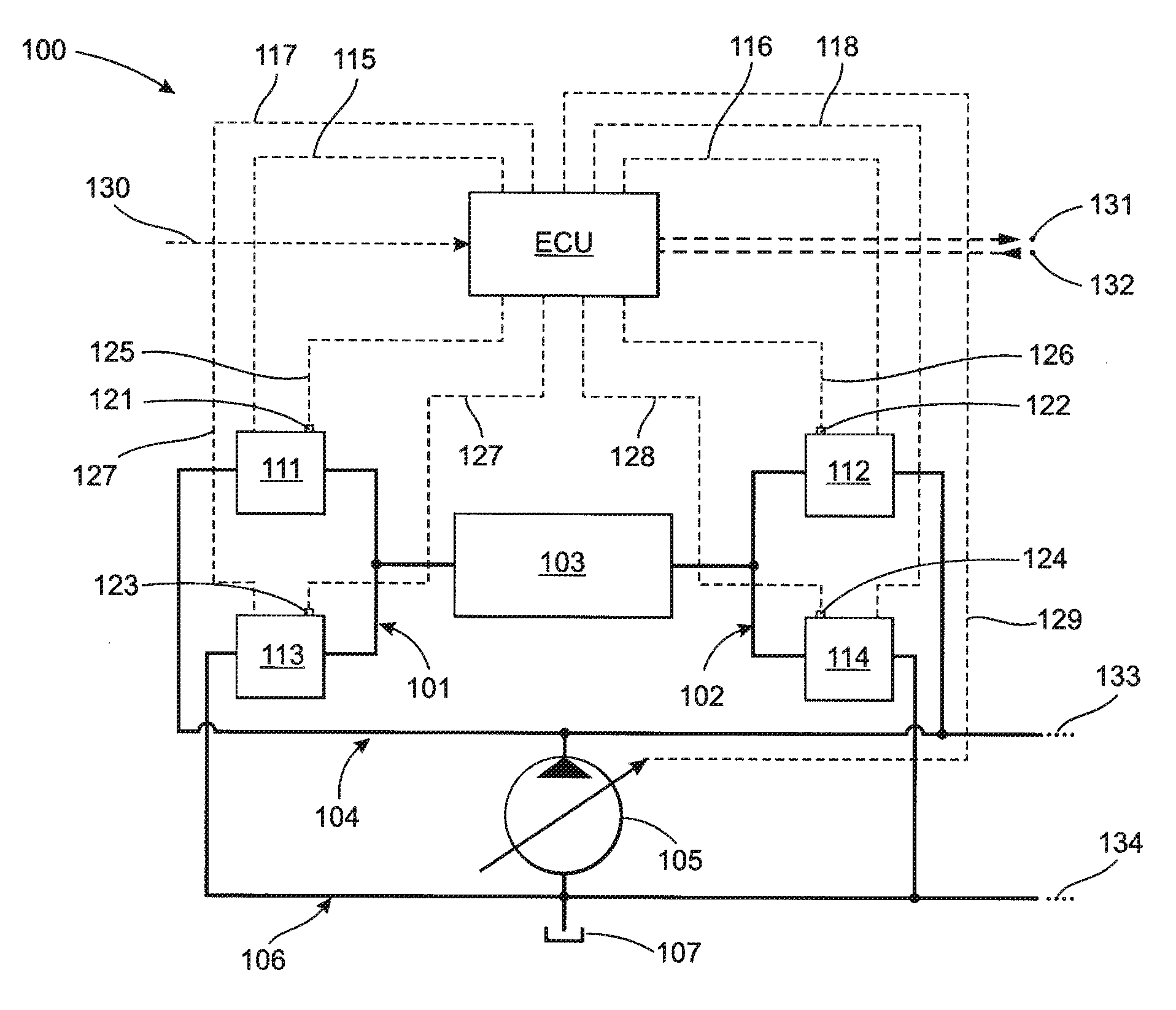
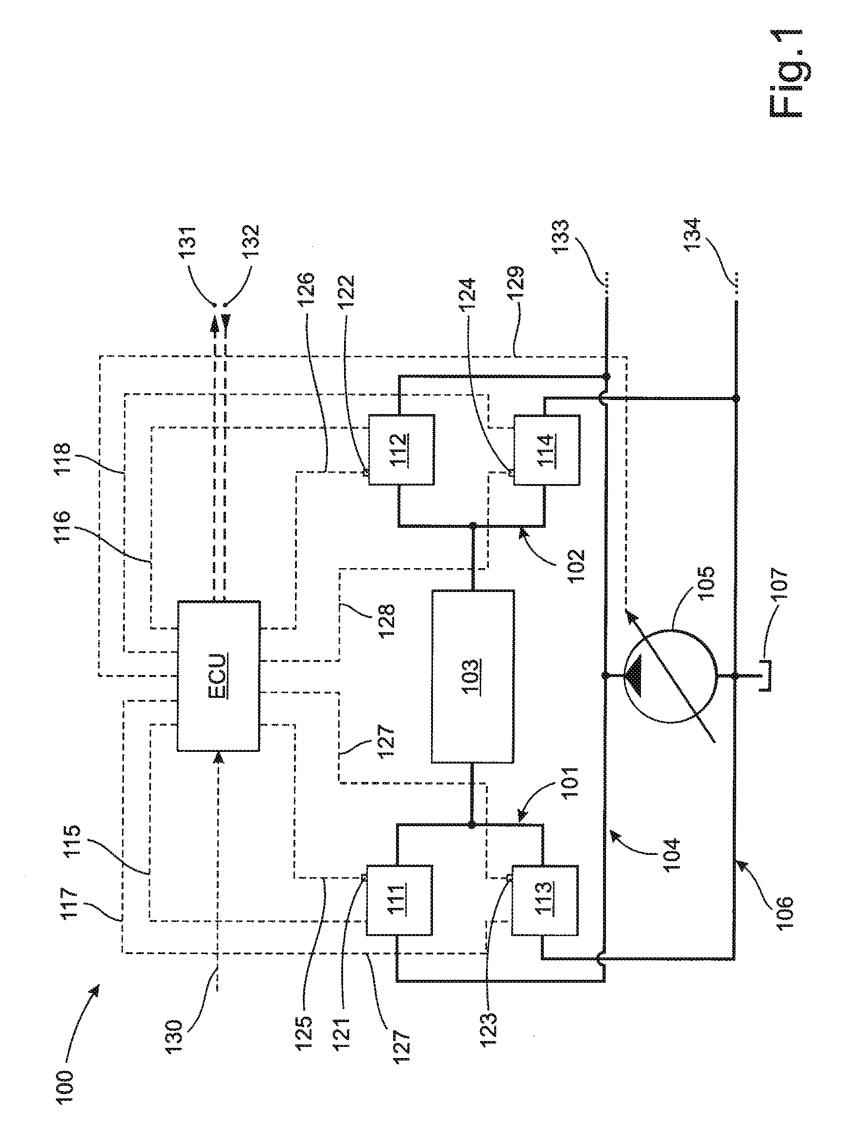
[0049]FIG. 1 shows a schematic diagram of a fluid arrangement 100 according to one embodiment of the invention. The fluid valve arrangement shown comprises a fluid conduit arrangement having a first conduit 101 and a second conduit 102, the first and the second conduits 101, 102 being connectable with a fluid consumer 103. The fluid valve arrangement further comprises a supply connection arrangement, having a pressure connection 104 supplied by a controllable pump 105, and a tank connection 106 for draining fluid to a tank 107. In this example, the source of pressure is a variable displacement fluid pump 105. Further, a first valve arrangement 111 is operable to accomplish at least one of closing the pressure connection 104 and connecting the pressure connection 104 in a controlled manner with the first conduit 101, and a second valve arrangement 112 is operable to accomplish at least one of closing the pressure connection 104 and connecting the pressure connection 104 in a controll...


PUM


Abstract

The invention relates to a method for controlling a fluid valve arrangement that includes a fluid conduit arrangement having a first conduit and a second conduit, the first and the second conduits being connectable with a fluid consumer; a supply connection arrangement having a pressure connection and a tank connection, and a number of valve arrangement for connecting the consumer to the pressure connection or the tank and a control device, which controls the valve arrangements. The method involves detecting output signals from opening degree sensors connected across at least the first and second valve arrangements to determine the magnitude and direction of a pressure drop across at least the first and second valve arrangements, and using the output signals to determine an operating mode for each valve arrangement.

Description

CROSS REFERENCE TO RELATED APPLICATION[0001]This application is a continuation of copending International Application PCT / SE2007 / 050485, filed Jul. 2, 2007, the disclosure of which is incorporated herein by reference in its entirety.TECHNICAL FIELD[0002]The invention relates to a fluid valve arrangement comprising a fluid circuit having a first conduit and a second conduit, both conduits being connectable with a fluid consumer, a supply connection arrangement having a pressure connection and a tank connection, a first valve arrangement, which closes the pressure connection or connects it in a controlled manner with the first conduit or the second conduit, a second valve arrangement, which closes the tank connection or connects it in a controlled manner with the first conduit or the second conduit, and a control device, which controls the first valve arrangement and the second valve arrangement.BACKGROUND ART[0003]A fluid valve arrangement comprising a control device such as a manual...

Claims


Application Information

Patent Timeline
IPC IPC(8): F15D1/00F16K31/12
CPCE02F9/2203E02F9/2228E02F9/2267E02F9/2296F15B11/006F15B2211/20546F15B2211/7053F15B2211/3144F15B2211/329F15B2211/40561F15B2211/40569F15B2211/634F15B2211/30575Y10T137/0396Y10T137/7761E02F9/22F15B13/042F15B21/08
Inventor ERIKSSON, BJORN
Owner PARKER HANNIFIN AB
Why Eureka
Try Eureka