Multireflection Time-Of-Flight Mass Spectrometer

a mass spectrometer and time-of-flight technology, applied in mass spectrometers, particle separator tubes, isotope separation, etc., can solve the problems of increasing the cost, increasing the cost, and increasing the pumping requirements, so as to improve the spatial focus. effect of

Active Publication Date: 2011-01-27
THERMO FISHER SCI BREMEN
View PDF6 Cites 18 Cited by
  • Summary
  • Abstract
  • Description
  • Claims
  • Application Information

AI Technical Summary

Benefits of technology

[0019]The electric field of the ion mirror may be arranged to enhance spatial focussing by causing the ions to undergo spatial compression at least once (and preferably twice) during passage through the ion mirror.
[0020]In one particularly preferred embodiment, the ion mirror forms part of a stack of ion mirrors together constituting a first ion mirror arrangement. A second ion mirror arrangement is also provided, opposed to the first ion mirror arrangement. Ions are directed into the first ion mirror of the first mirror arrangement where they reflect back towards the second ion mirror arrangement, and are then reflected int

Problems solved by technology

However, beyond a certain linear separation, practical problems arise as the instrument size increases, leading to increased cost, additional pumping requirements, and so forth.
The problem with such an arrangement is that it severely limits the mass range that can be analyzed.
On increasing separation this train of pulses separates to such an extent that ions at the front of the train reach around to the back of the train, and ion mixing begins which complicates m/z analysis of those ions.
Although the arrangement of Wollnik addresses the limited mass range of other prior art devices, it does not offer a practical solution which could implement the large number of ion mirrors in the case where a large ion inci

Method used


Image

  • Multireflection Time-Of-Flight Mass Spectrometer
  • Multireflection Time-Of-Flight Mass Spectrometer
  • Multireflection Time-Of-Flight Mass Spectrometer

Examples


Embodiment Construction

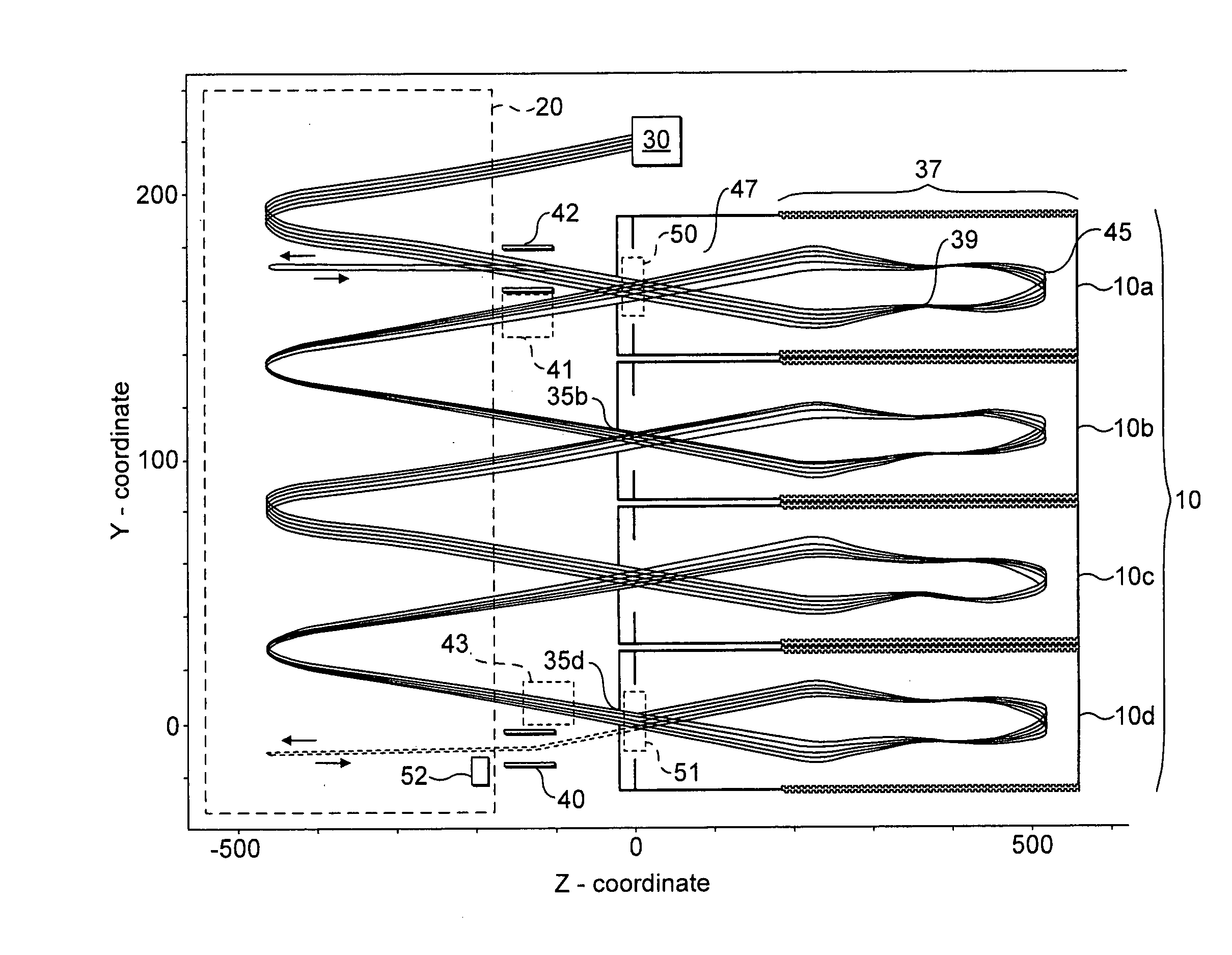
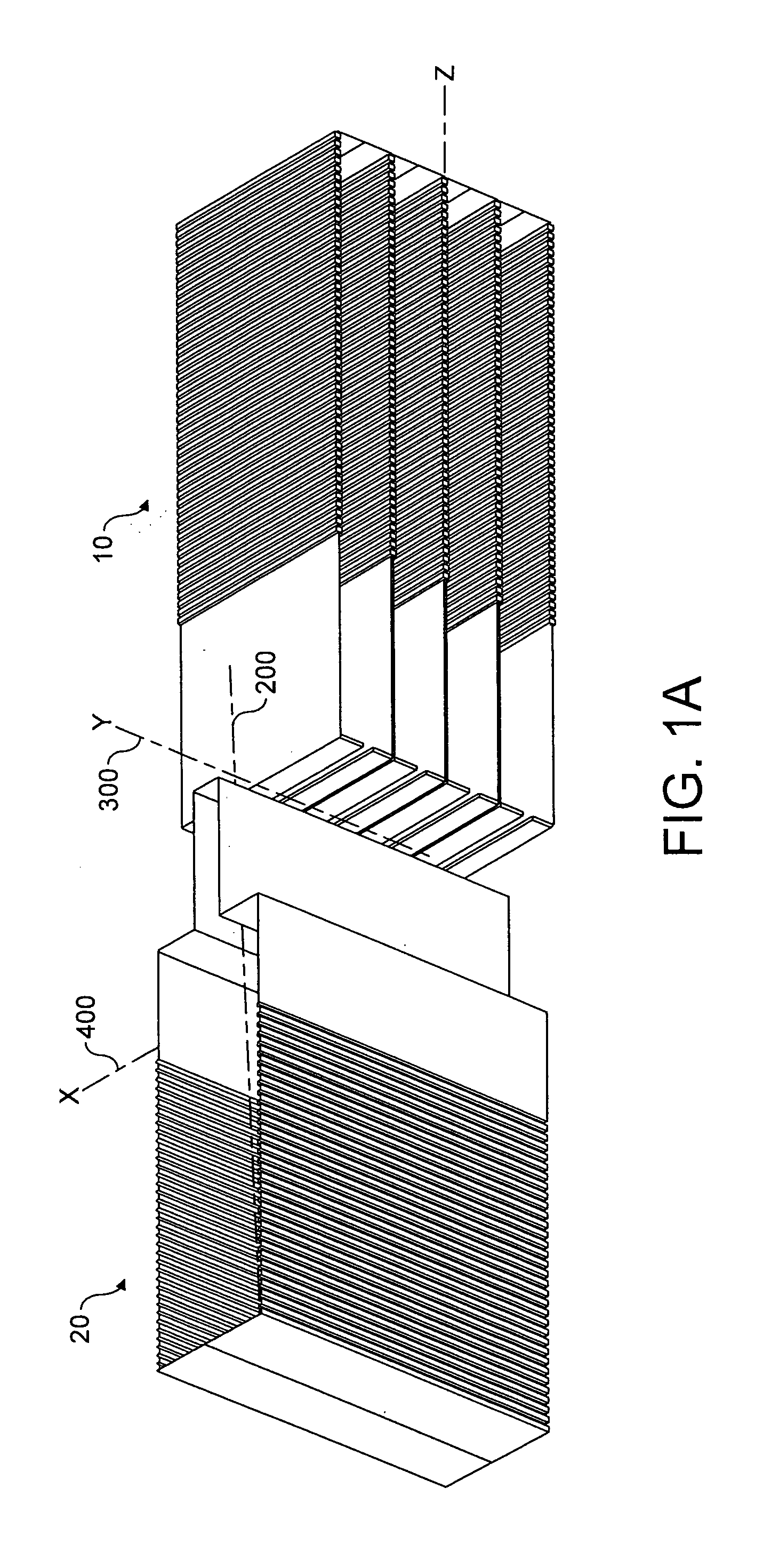
[0063]FIG. 1A shows a third angle projection (perspective) view of a multireflection time of flight mass spectrometer (MR TOF MS). The MR TOF MS includes two separate ion mirror arrangements. The first ion mirror arrangement 10 forms one of a pair of systems of planar mirrors which are designated “Type 1” in the following description. The MR TOF MS of FIG. 1 also includes a second ion mirror arrangement 20 which is generally orthogonal with the first ion mirror 10 and designated “Type 2” in the following description.

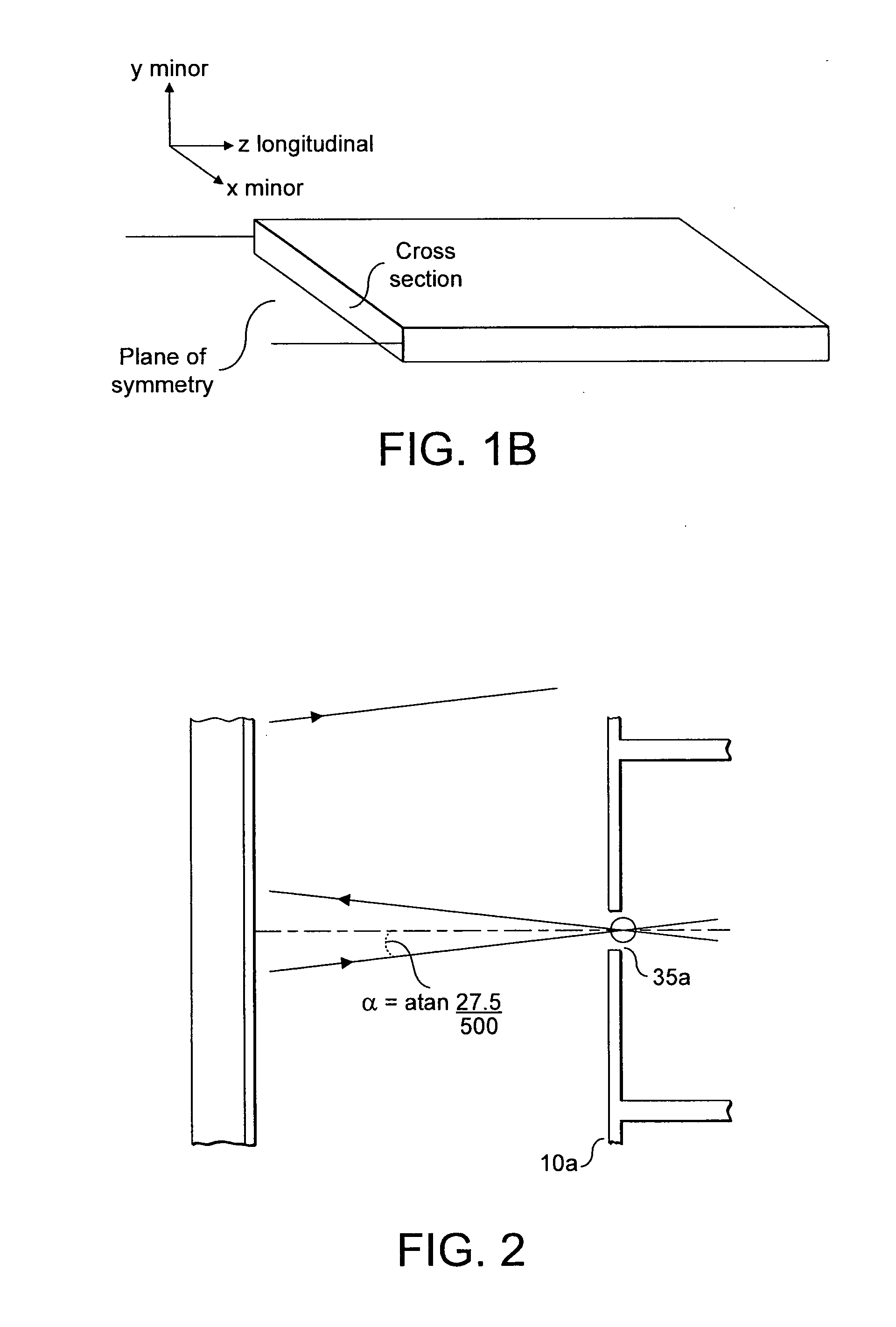
[0064]It will be noted that the first ion mirror arrangement 10 comprises, in the preferred embodiment of FIG. 1A, four ion mirrors stacked on top of each other in a direction parallel with the Y axis 300 as shown in FIG. 1A. FIG. 1B shows a single mirror of the first ion mirror arrangement. Each ion mirror comprises a set of electrodes (a preferred embodiment of which is shown in FIG. 5 below) which, when energized, create an electric field within each ion mirror. It wi...


PUM


Abstract

The present invention provides a method of reflecting ions in a multireflection time of flight mass spectrometer comprising providing an ion mirror having a plurality of electrodes, the ion mirror having a cross section with a first, minor axis (Y) and a second, major axis (X) each perpendicular to a longitudinal axis (Z) of the ion mirror which lies generally in the direction of time of flight separation of the ions in the mirror; guiding ions towards the ion mirror; applying a voltage to the electrodes so as to create an electric field which: (a) causes the mean trajectory of the ions to intersect a plane of symmetry of the ion mirror which contains the longitudinal (Z) and major axes (X) of the mirror; (b) causes the ions to reflect in the ion mirror; and (c) causes the ions to exit the ion mirror in a direction such that the mean trajectory of ions passing through the ion mirror has a component of movement in a direction (Y) perpendicular to and diverging from the said plane of symmetry thereof.

Description

FIELD OF THE INVENTION[0001]This invention relates to a multireflection time-of-flight (TOF) mass spectrometer.BACKGROUND OF THE INVENTION[0002]Mass spectrometry is a well known analytical tool for identification and quantitative analysis of elements, compounds and so forth. The key qualities of a mass spectrometer are its resolving power, mass accuracy and sensitivity. One specific form of mass spectrometry, time-of-flight mass spectrometry (TOF-MS) involves accelerating ions in an electric field and then drifting them to a detector at a known distance. Ions of different mass to charge ratios (m / z) but having the same kinetic energy move at different velocities towards the detector and so separate according to their m / z.[0003]The resolving power of TOF-MS is typically related to the flight length: the longer the distance between the location of ion packet formation and the detector, the greater the resolving power. To an extent, therefore, the resolution of a TOF-MS can be improved...

Claims


Application Information

Patent Timeline
IPC IPC(8): H01J49/40
CPCH01J49/406H01J49/061H01J49/405
Inventor MAKAROV, ALEXANDER A.GRINFIELD, DMITRY E.MONASTYRSKIY, MIKHAIL A.
Owner THERMO FISHER SCI BREMEN
Why Eureka
Try Eureka