Radiation image conversion panel and production method thereof

a technology of conversion panel and radiation image, which is applied in the direction of conversion screen, fluorescence/phosphorescence measurement, optical radiation measurement, etc., can solve the problems of insufficient spatial resolution, insufficient image sharpness, inability to realize free image processing or instantaneous image transfer, etc., to improve moisture resistance and shock resistance, and enhance sharpness

Active Publication Date: 2011-01-27
KONICA MINOLTA MEDICAL & GRAPHICS INC
View PDF24 Cites 14 Cited by
  • Summary
  • Abstract
  • Description
  • Claims
  • Application Information

AI Technical Summary

Benefits of technology

[0022]According to the present invention, there can be provided a radiation image conversion panel which can obtain a radiation image with enhanced sharpness, has achieved improved moisture resistance and shock resistance and comprises, on a support, a phosphor layer containing phosphor columnar crystals formed by a process of gas phase deposition.
[0023]The reason for achieving improvements in moisture resistance and shock resistance is not clear but it is supposed that when the coefficient of variation of the crystal diameters of the phosphor columnar crystals is more than 50% and the coefficient of variation of the phosphor filling factors of the phosphor layer is more than 20%, phosphor particles are locally fused, resulting in disorder in the columnar crystal structure or generating voids in the phosphor layer and areas in the vicinity thereof are easily damaged by local humidity or shock, leading to deterioration in humidity resistance or shock resistance.

Problems solved by technology

However, these image data are so-called analog image data, in which free image processing or instantaneous image transfer cannot be realized.
However, image sharpness is insufficient and spatial resolution is also insufficient, which have not yet reached the image quality level of the conventional screen / film system.
A thicker phosphor layer causes more scattering of emission within the phosphor layer, leading to deteriorated sharpness.
However, the use of cesium iodide (CsI) alone results in reduced emission efficiency.
However, a scintillator (also referred to as a phosphor layer) based on cesium iodide (CsI) exhibits deliquescence and suffered a disadvantage of characteristics being deteriorated with aging.
Recently, in a flat panel type radiation detector (FDP, or also referred to as a radiation image conversion panel) employing cesium iodide (CsI), a larger flat panel or a portable cassette type panel have been required and levels of requirements for moisture resistance or shock resistance have become severe, compared to computed radiography (CR) employing a photostimulable phosphor, so that the prior art, as described above was not able to satisfy the required levels.

Method used


Image

  • Radiation image conversion panel and production method thereof
  • Radiation image conversion panel and production method thereof

Examples


example 1

Preparation of Scintillator Panel

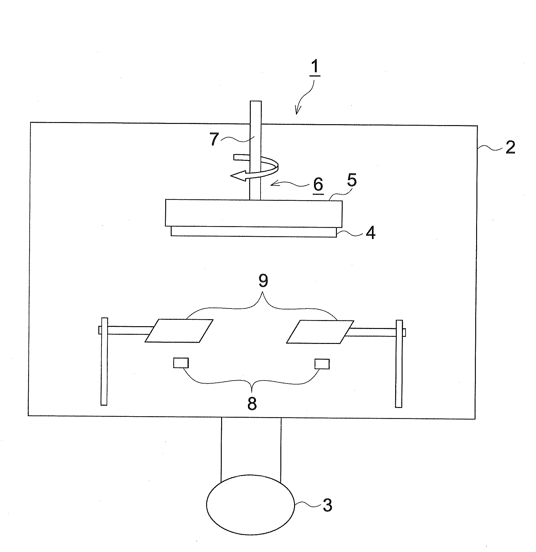
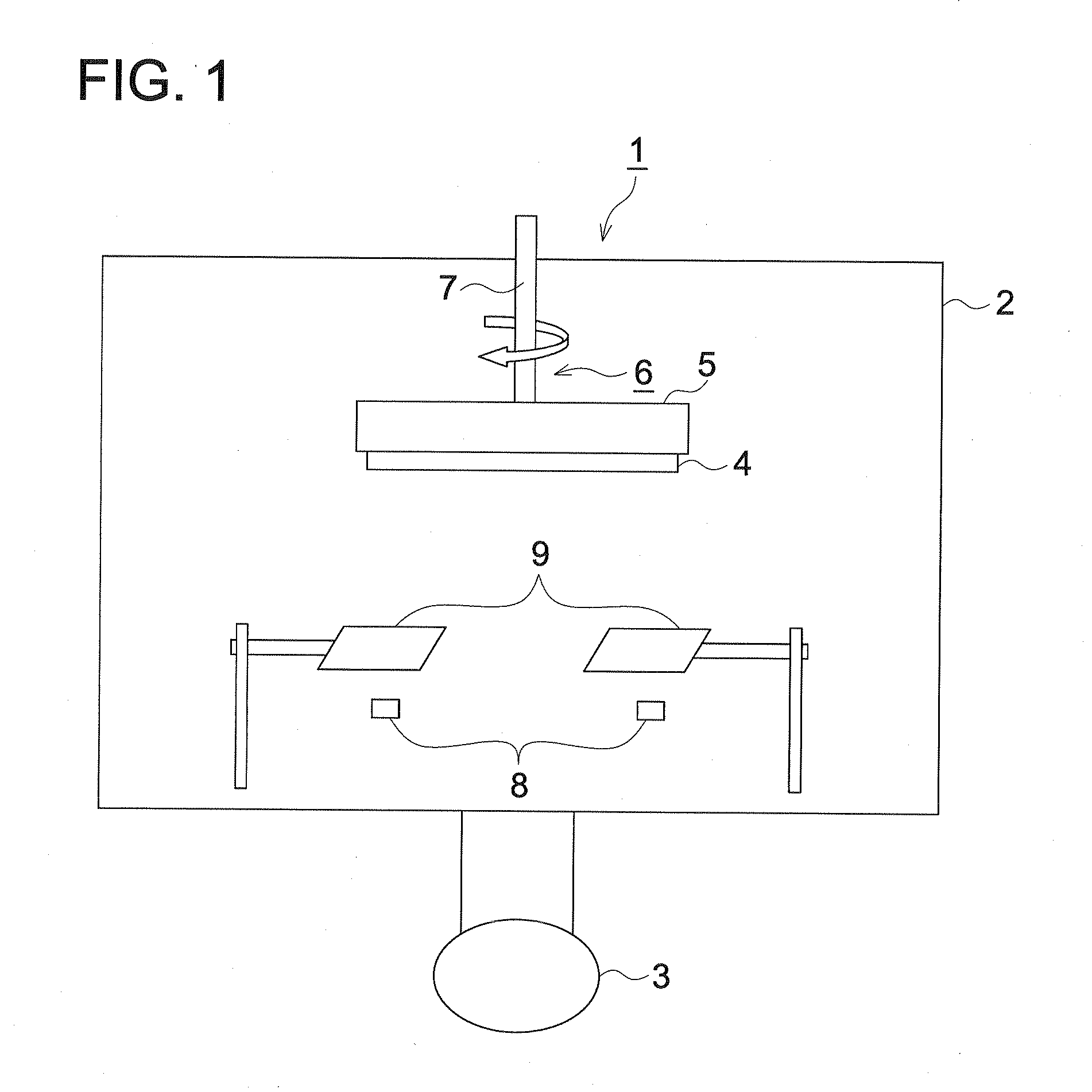
[0132]Phosphor 1 (CsI alone) and phosphor 2 (CsI:0.003Tl) were vapor-deposited, on one side of a support comprised of a polyimide resin sheet, to form a phosphor layer. Specifically, first, a support is placed on a support holder provided with a support rotation mechanism. Then, the foregoing phosphor raw materials were placed in evaporation source crucibles. Two evaporation source crucibles were disposed in the vicinity of the bottom of the vacuum vessel and on the circumference of a circle centered on a center line vertical to the support. The distance between the support and the evaporation source was adjusted to 300 mm and the distance between the center line vertical to the support and the evaporation source was adjusted to 300 mm. Subsequently, after the interior of the vacuum vessel was evacuated, the vacuum degree was adjusted to 0.1 Pa, while introducing Ar gas and the temperature of the support was maintained at 30° C., while rotating the s...

example 2

[0134]A scintillator panel was obtained in the same manner as in Example 1, except that the distance between the support and the evaporation source was adjusted to 500 mm.

example 3

[0135]A scintillator panel was obtained in the same manner as in Example 1, except that the distance between the support and the evaporation source was adjusted to 700 mm.


PUM

PropertyMeasurementUnit
melting pointaaaaaaaaaa
thicknessaaaaaaaaaa

Abstract

Disclosed are a radiation image conversion panel which has achieved a radiation image with enhanced sharpness and improved moisture resistance and shock resistance, and a production method thereof. The radiation image conversion panel comprises, on a support, a phosphor layer comprising phosphor columnar crystals, each composed mainly of cesium iodide (CsI) and formed by a process of gas phase deposition, wherein a coefficient of variation of crystal diameter of the phosphor columnar crystals is not more than 50% and a coefficient of variation of phosphor filling factor of the phosphor layer is not more than 20%.

Description

TECHNICAL FIELD[0001]The present invention relates to a radiation image conversion panel enabling to obtain a radiation image with enhanced sharpness and achieving improved moisture resistance and shock resistance, and a production method thereof.TECHNICAL BACKGROUND[0002]There have been broadly employed radiographic images such as X-ray images for diagnosis of the conditions of patients on the wards. Specifically, radiographic images using an intensifying-screen / film system have achieved enhancement of speed and image quality over its long history and are still used on the scene of medical treatment as an imaging system having high reliability and superior cost performance in combination. However, these image data are so-called analog image data, in which free image processing or instantaneous image transfer cannot be realized.[0003]Recently, there appeared digital system radiographic image detection apparatuses, as typified by a computed radiography (also denoted simply as CR) and...

Claims


Application Information

Patent Timeline
Patent Type & Authority Applications(United States)
IPC IPC(8): G01T1/20C23C16/22C23C16/06C23C16/44
CPCC09K11/628G21K4/00C23C14/26C23C14/0694
Inventor KASAI, SHIGETAMIISA, HIROSHIIIJIMA, MAKOTONAGATA, YASUSHI
Owner KONICA MINOLTA MEDICAL & GRAPHICS INC
Why Eureka
Try Eureka