Digital pulse width modulated motor control system and method

a digital and pulse width modulation technology, applied in the direction of motor/generator/converter stopper, dynamo-electric converter control, ac motor stopper, etc., can solve the problems of significant inefficiencies in the motor control system, and the maximum forward and reverse pulse had only a 50% duty cycle, so as to improve the motor control

Active Publication Date: 2011-01-27
KOBAYASHI HERBERT S
View PDF32 Cites 9 Cited by
  • Summary
  • Abstract
  • Description
  • Claims
  • Application Information

AI Technical Summary

Benefits of technology

[0032]It is an object of the present invention to provide an improved motor control.

Problems solved by technology

Prior art motor control systems generally operate with significant inefficiencies such as high heat dissipation, and / or have problems related to changing the motor rotation direction.
However, a disadvantage of the circuitry taught in my previous patent is that the maximum forward and reverse pulse had only a 50% duty cycle.

Method used


Image

  • Digital pulse width modulated motor control system and method
  • Digital pulse width modulated motor control system and method
  • Digital pulse width modulated motor control system and method

Examples


Embodiment Construction

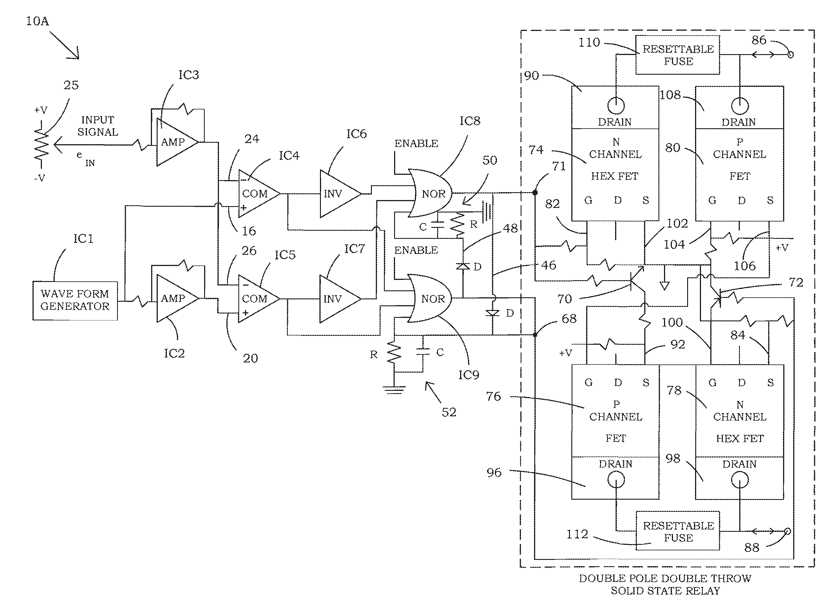
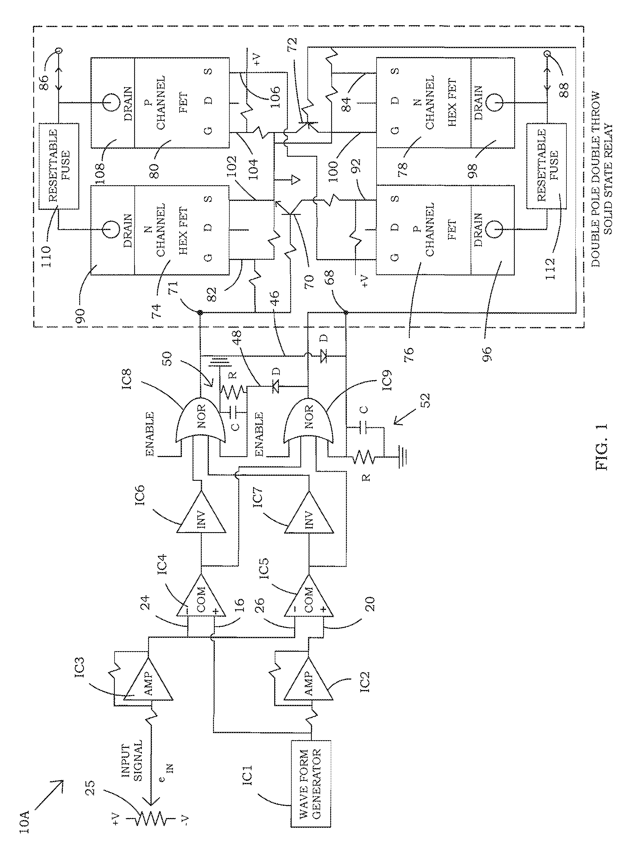
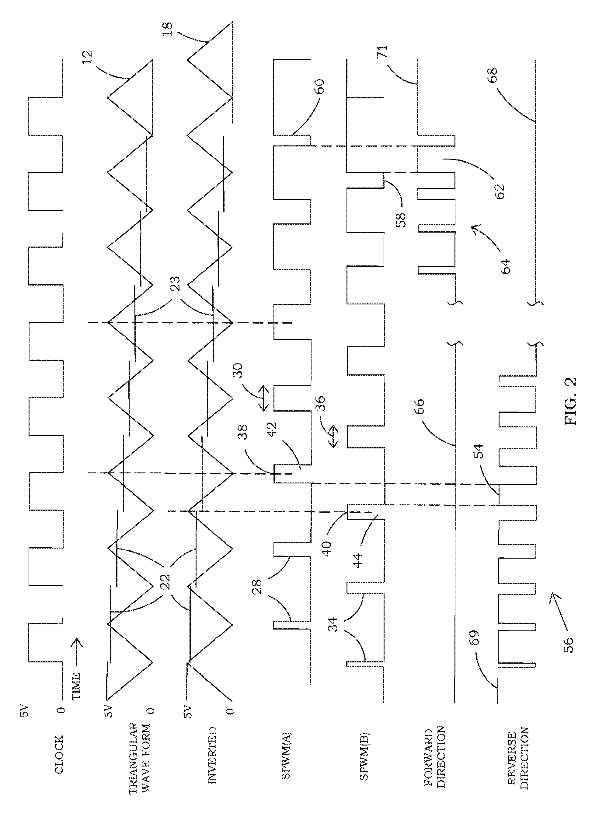
[0051]The present invention provides linear motor control using pulse width modulation. In one embodiment, two streams of pulse width modulated pulses are produced. The streams of pulses are staggered in that they begin at different times. Due to the logic circuit which combines the two streams of pulses, as the pulse widths change from small to large, the motor rotates at a high speed in one direction, slows down, stops, and then increases speed in the opposite direction. Different types of pulse generators may be utilized in accord with the present invention. Different types of triggers for the pulse generators may be utilized. The system provides low power loss, low cost, low weight, and increased efficiency of the motor speed control system.

[0052]Referring now to the drawings and more particularly to FIG. 1 and FIG. 4, there are shown circuit diagrams for motor control 10A and 10B which utilize two different types of variable width pulse generators, but which may use similar typ...


PUM


Abstract

A digital motor control system utilizes at least two variable pulse generators to produce two streams of pulse width modulated pulses to control the motor speed and direction of rotation of a motor. An input control signal may be compared with two reference signals, such as two waveforms which are inverted with respect to each other, to produce two streams of pulse width modulated signals. A logic circuit combines the two streams of pulses. In one embodiment, depending on the input control signal level, where the two streams do not overlap, reverse motor control signals are produced and where the two streams overlap, forward motor control signals are produced. As the pulse widths of the pulse width modulated pulses change, the motor may receive continuous power in one direction, slow down, stop, and then increase speed in the opposite direction until it receives continuous power in the other direction. The variable pulse generators may be of various types including one-shot multivibrators and comparators. In one embodiment, two sets of N-channel and P-channel power switches may be utilized to drive the motor.

Description

BACKGROUND OF THE INVENTION[0001]1. Field of the Invention[0002]The present invention relates generally to motor control systems and, more particularly, to a multiple pulse width modulation digital motor control system to control both the motor speed and direction of rotation for D.C. or A.C. electric motors.[0003]2. Description of the Background[0004]Prior art motor control systems generally operate with significant inefficiencies such as high heat dissipation, and / or have problems related to changing the motor rotation direction. The circuitry shown in my previous U.S. Pat. No. 7,421,193, which is incorporated in its entirety herein by reference, discloses a motor control with very low heat dissipation, which in one embodiment provides a controller for speed and motor direction. However, a disadvantage of the circuitry taught in my previous patent is that the maximum forward and reverse pulse had only a 50% duty cycle.[0005]For a servo power control system to operate reliably with...

Claims


Application Information

Patent Timeline
Patent Type & Authority Applications(United States)
IPC IPC(8): H02P29/00
CPCH02M7/53873H02P7/29H02P27/08Y02E50/10
Inventor KOBAYASHI, HERBERT S.
Owner KOBAYASHI HERBERT S
Why Eureka
Try Eureka