
Chemical hydride formulation and system design for controlled generation of hydrogen

a technology of chemical hydride and hydrogen, applied in the field of fuel cells, can solve the problems of increasing the complexity of the system, reducing the overall energy density, and limited application of fuel cell systems for commercial products, and achieve the effect of reducing caking and precipitation

Inactive Publication Date: 2011-01-27
INTELLIGENT ENERGY LTD
View PDF101 Cites 33 Cited by
  • Summary
  • Abstract
  • Description
  • Claims
  • Application Information

AI Technical Summary

Benefits of technology

[0006]The present invention provides a chemical hydride liquid reactant distribution mixture. The mixture includes a fuel mixture having at least one hydride and at least one activating agent. The invention further includes a liquid-distributing agent (LDA), a form-stabilizing agent, and at least one anti-caking agent. The liquid reactant distribution mixture reduces caking and precipitation while promoting liquid reactant distribution, where the chemical hydride liquid reactant distribution mixture generates hydrogen via hydrolysis.

Problems solved by technology

However, due to the lack of proper storage means of a fuel, hydrogen in most cases, applications of fuel cell systems for commercial products have been limited.
In addition, need for extra materials (e.g. sodium hydroxide) to stabilize the fuel leads to increased complexity of the system and a decrease in overall energy density.
This phase change may result in precipitation at unwanted locations, leading to the failure of the entire system.
Although this method intends to provide control of the reactant liquid using spatial and form-factor variation of the conduits, construction of such a system may become complex and also lead to decrease in total energy density of the system.
In addition, this system has not addressed serious issues such as the caking and precipitation of reaction products, which are detrimental to the performance of any hydrogen system based on solid chemical hydride.
Furthermore, despite the high energy density of SBH material itself, the energy density of a hydrogen generator system using the SBH often decreases due to added components or increased volume of the system for reaction control and product filtration.

Method used


Image

  • Chemical hydride formulation and system design for controlled generation of hydrogen
  • Chemical hydride formulation and system design for controlled generation of hydrogen
  • Chemical hydride formulation and system design for controlled generation of hydrogen

Examples


Embodiment Construction

[0051]Although the following detailed description contains many specifics for the purposes of illustration, anyone of ordinary skill in the art will readily appreciate that many variations and alterations to the following exemplary details are within the scope of the invention. Accordingly, the following preferred embodiment of the invention is set forth without any loss of generality to, and without imposing limitations upon, the claimed invention.

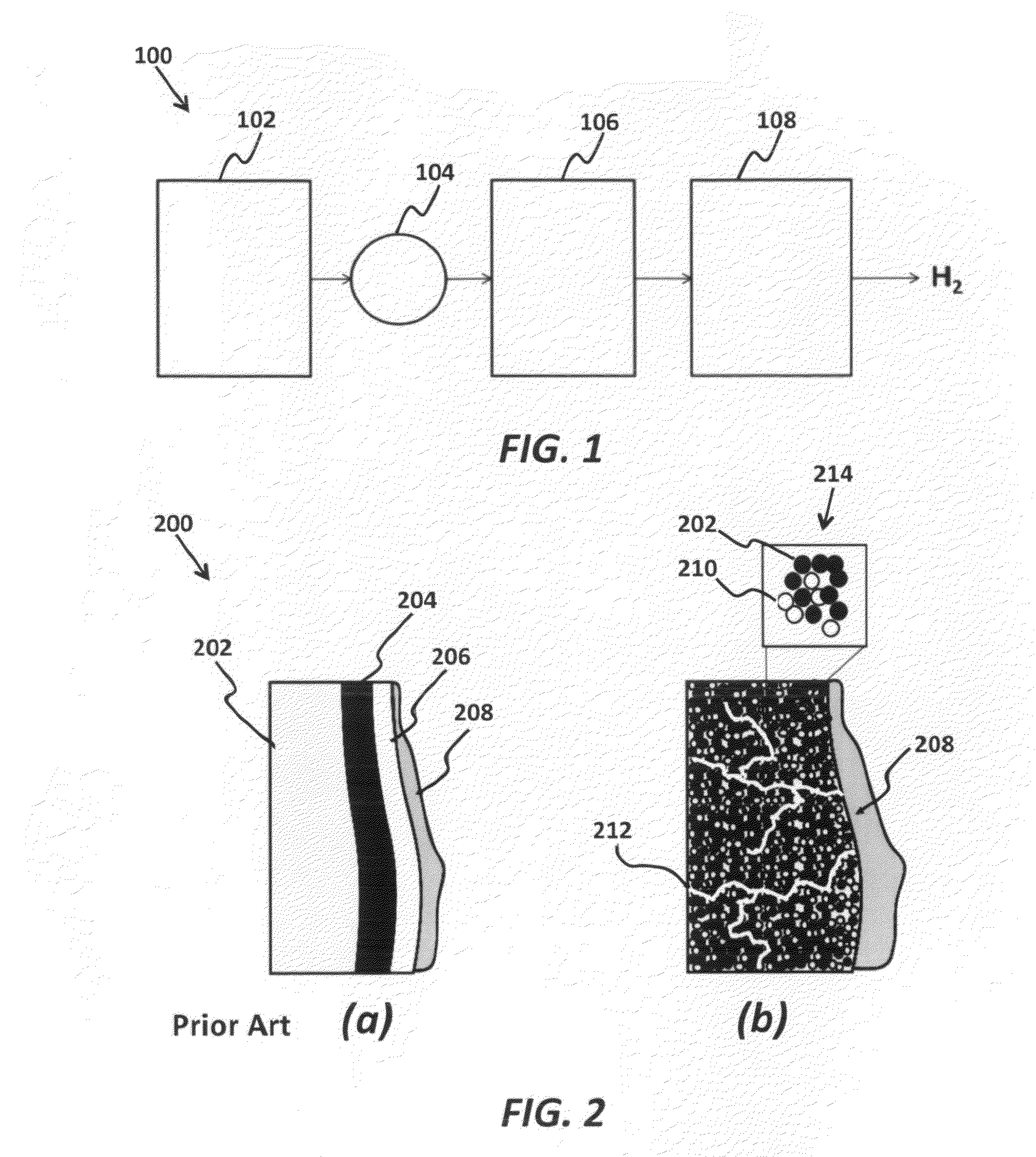
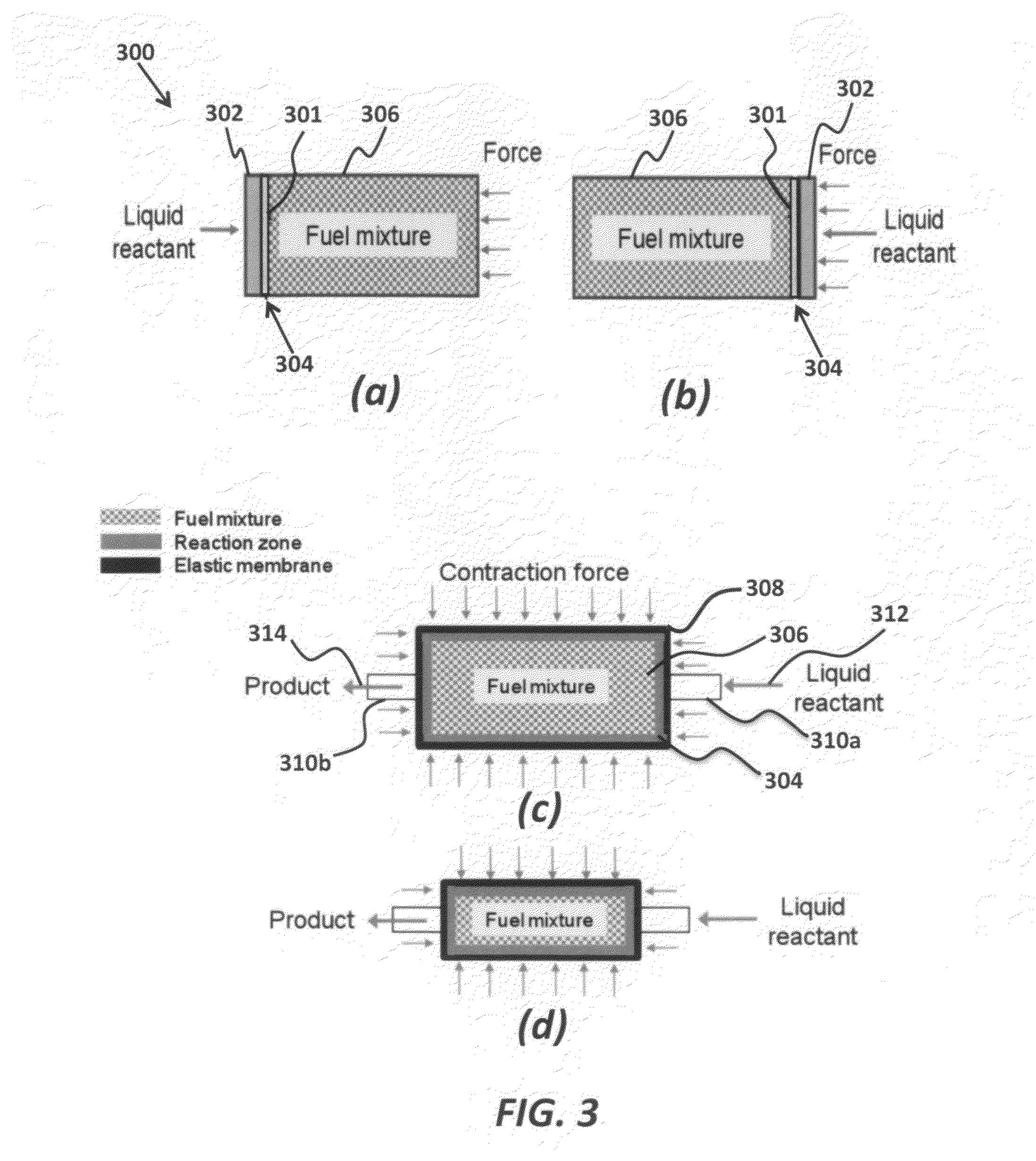
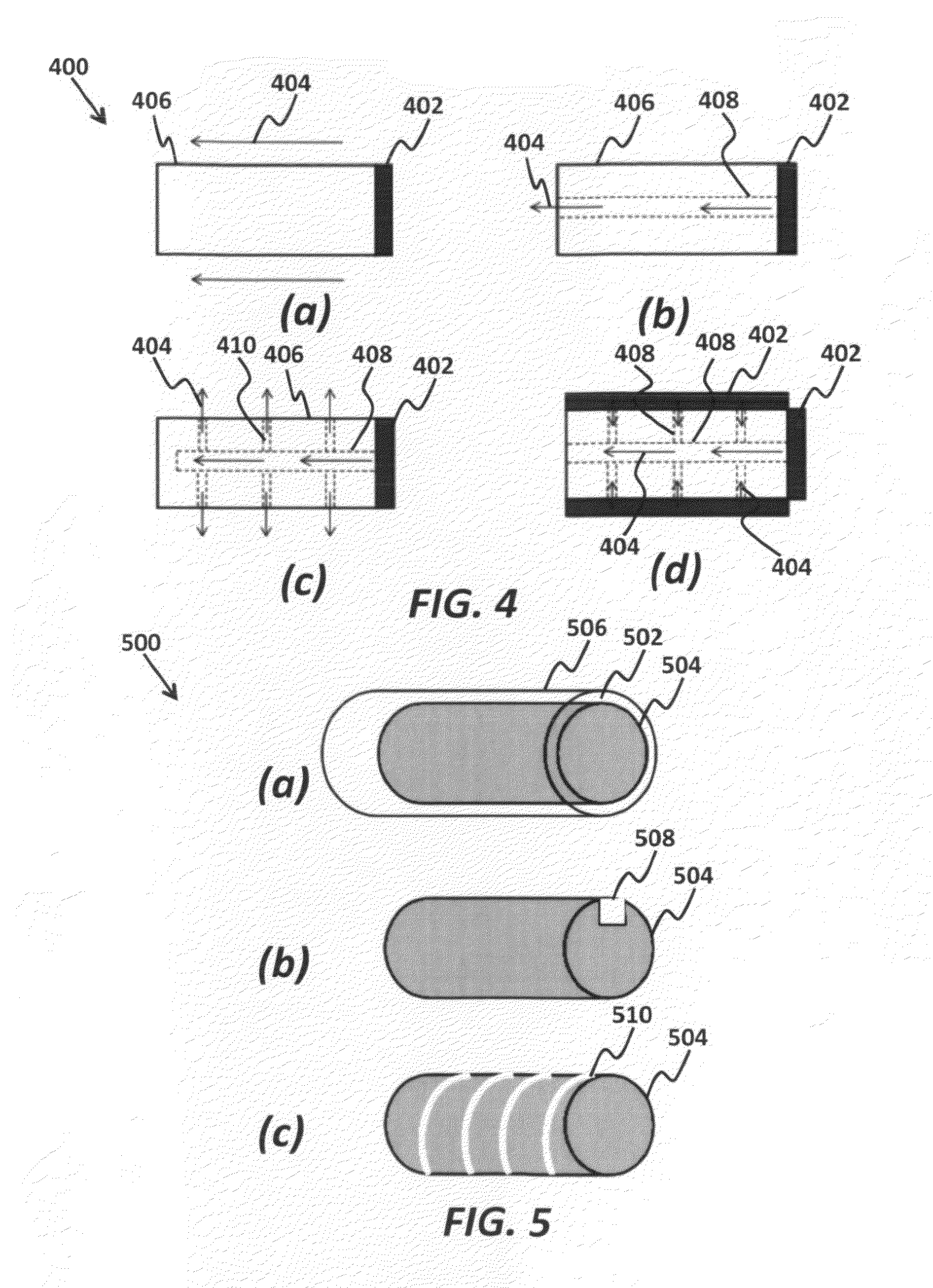
[0052]The present invention provides a hydrogen generator system optimized for portable applications with the emphasis on novel fuel mixture that enhances the energy density, controllability, low cost, safety, and environmental friendliness. In addition, for system miniaturization, this invention also presents system architectures, reaction control mechanisms and their appropriate materials, and filtration designs and their suitable materials. In particular, these inventions are optimized for the non-liquid fuel mixture described above.

[0...


PUM


Abstract

A chemical hydride liquid reactant distribution mixture is provided. The mixture includes a fuel mixture having at least one hydride and at least one activating agent. The invention further includes a liquid-distributing agent (LDA), a form-stabilizing agent, and at least one anti-caking agent. The liquid reactant distribution mixture reduces caking and precipitation while promoting liquid reactant distribution, where the chemical hydride liquid reactant distribution mixture generates hydrogen via hydrolysis.

Description

FIELD OF THE INVENTION[0001]The invention relates generally to fuel cells. More particularly, the invention relates to chemical hydride liquid reactant distribution mixtures for reducing caking and precipitation while promoting liquid reactant distribution.BACKGROUND[0002]Fuel cells, as an alternative source of electric energy, have been explored extensively. However, due to the lack of proper storage means of a fuel, hydrogen in most cases, applications of fuel cell systems for commercial products have been limited. In particular, for mobile applications such as laptops, mp3 players, or cellular phones, demand for portable hydrogen storage that is safe and high in energy density has grown significantly. Among many chemical hydride systems, sodium borohydride (SBH) as a source of hydrogen has been the most studied and understood. SBH reacts with water and becomes hydrolyzed releasing molecular hydrogen gas. This SBH hydrolysis is typically accelerated using catalytic materials or ac...

Claims


Application Information

Patent Timeline
IPC IPC(8): C01B3/04C01B3/00
CPCY02E60/362C01B3/065Y02E60/36
Inventor RYU, WONHYOUNGBRAITHWAITE, DANIELFABIAN, TIBOR
Owner INTELLIGENT ENERGY LTD
Learn More