Apparatus and method for reducing the standby power consumption of a display, and display with low standby power consumption
- Summary
- Abstract
- Description
- Claims
- Application Information
AI Technical Summary
Benefits of technology
Problems solved by technology
Method used
Image
Examples
first embodiment
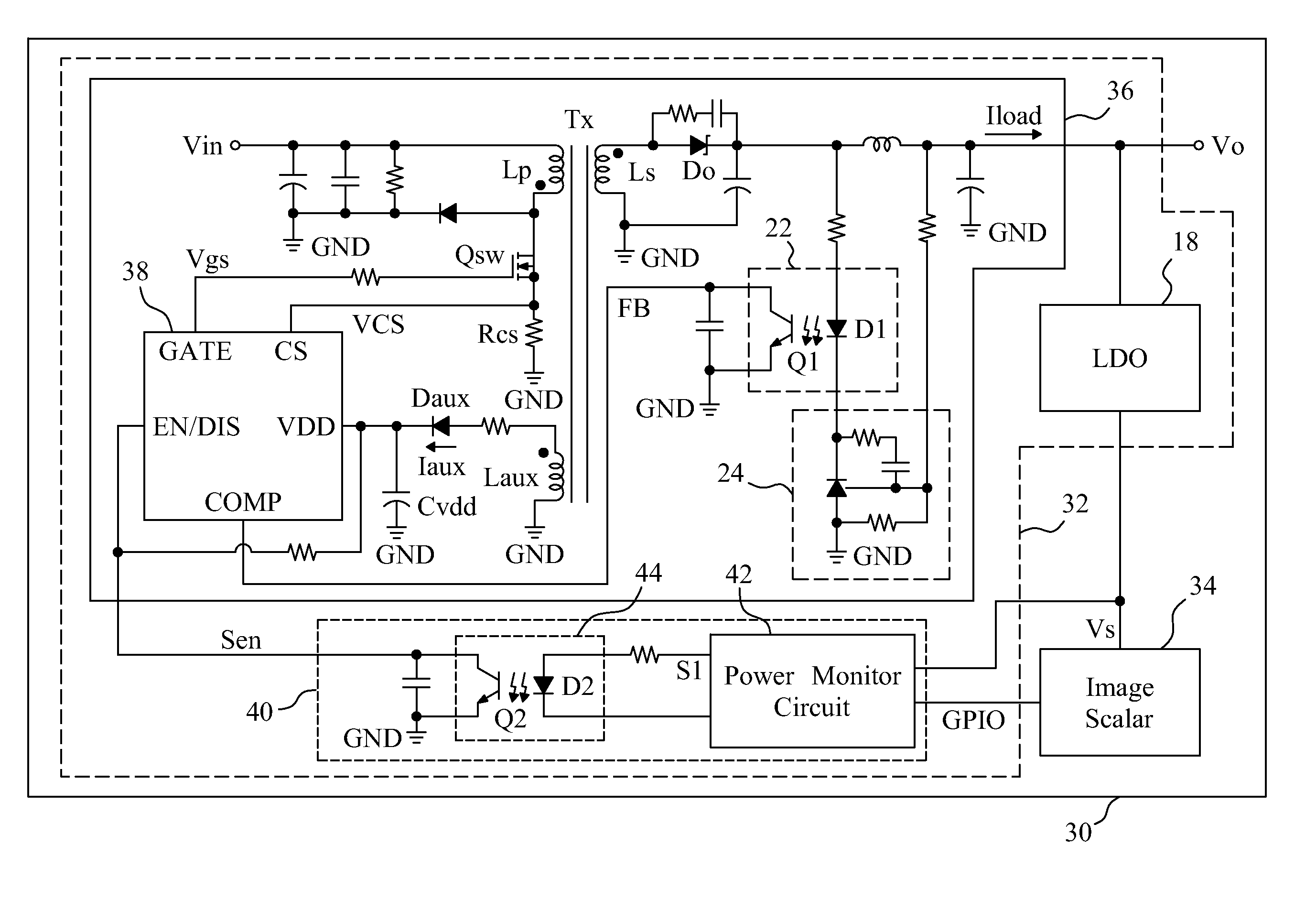
[0017]FIG. 4 is a circuit diagram of a first embodiment for the power monitor circuit 42, which includes a hysteresis comparator 46 and a logic circuit 48. An upper threshold value Power_High and a lower threshold value Power_Low are provided for the input of the hysteresis comparator 46 to define the upper limit and the lower limit of a hysteresis band, respectively. The voltage Vs is compared with the upper and lower limits to generate a comparison signal Sc. In the logic circuit 48, an AND gate generates a first signal S2 according to the comparison signal Sc and the mode signal GPIO, an inverter 52 is connected to the AND gate 50 to generate a second signal S3 by inverting the first signal S2, and an AND gate 54 generates the control signal S1 according to the mode signal GPIO and the second signal S3.
second embodiment
[0018]FIG. 5 is a circuit diagram of a second embodiment for the power monitor circuit 42, in which the hysteresis comparator 46 is identical to its counterpart in the embodiment shown in FIG. 4, and a logic circuit 56 includes an AND gate 58 to generate a first signal S4 according to the comparison signal Sc and the mode signal GPIO, an inverter 60 to generate a second signal S5 by inverting the mode signal GPIO, an OR gate 62 connected to the AND gate 58 and the inverter 60 to generate a third signal S6 according to the first signal S4 and the second signal S5, and an inverter 64 connected to the OR gate 62 to generate the control signal S1 by inverting the third signal S6. The logic circuit 56 of FIG. 5 generates the same operation result as the logic circuit 48 of FIG. 4. A person skilled in the art can design other logic circuits based on the teachings of the foregoing embodiments.
[0019]FIG. 6 is a waveform diagram of the display 30 employing the power monitor circuit 42 of FIG...
PUM
 Abstract
Description
Claims
Application Information
 - R&D
- Intellectual Property
- Life Sciences
- Materials
- Tech Scout
- Unparalleled Data Quality
- Higher Quality Content
- 60% Fewer Hallucinations
Browse by: Latest US Patents, China's latest patents, Technical Efficacy Thesaurus, Application Domain, Technology Topic, Popular Technical Reports.
© 2025 PatSnap. All rights reserved.Legal|Privacy policy|Modern Slavery Act Transparency Statement|Sitemap|About US| Contact US: help@patsnap.com


