
Heat pump with intgeral solar collector

a solar collector and heat pump technology, applied in the field of heat pump systems, can solve the problems of reducing the efficiency of heat pump, and reducing the requirement for oil lubrication, so as to reduce the density, increase the pressure, and reduce the effect of capital cos

Inactive Publication Date: 2011-02-10
SOL XORCE
View PDF21 Cites 69 Cited by
  • Summary
  • Abstract
  • Description
  • Claims
  • Application Information

AI Technical Summary

Benefits of technology

"The present invention is about using expandable fluids in thermally activated processes. These fluids have the unique property of becoming less dense as they get hotter, which means they can compress more easily. This compression is done using a heat pump, which is a device that converts heat into mechanical energy. By using solar energy or other external fuels to heat the expandable fluid, the invention reduces the cost of the energy needed for the process. The change in density also allows the heat pump to regulate the inventory of fluid within the system, which helps improve the efficiency of the process."

Problems solved by technology

Furthermore by definition solar energy is a function of solar intensity and thus at the minimum is absent during the nighttime, unless significant thermal storage is utilized that is currently very expensive.
In addition, traditional solar collectors, particularly flat panel collectors, are temperature constrained due in large part to declining efficiencies as a function of temperature and the degradation of the working fluid which is often a mixture of a glycol and water.
Heat pumps also have significant limitations that limit temperature including the requirement for oil lubrication that would suffer oxidative destruction at the higher temperatures desired within heat pumps.
The combined limitations of each individual component being the solar collector and the heat pump presents significant challenges that are further exasperated when high integration using the same working fluid for both devices is realized.
The traditional solar systems utilize a working fluid that is a heat transfer fluid and thus isn't directly compatible as a thermodynamic cycle working fluid.
Furthermore by definition solar energy is a function of solar intensity and thus at the minimum is absent during the nighttime, unless significant thermal storage is utilized that is currently very expensive, the system will experience substantial changes in density according to operating and ambient conditions.

Method used

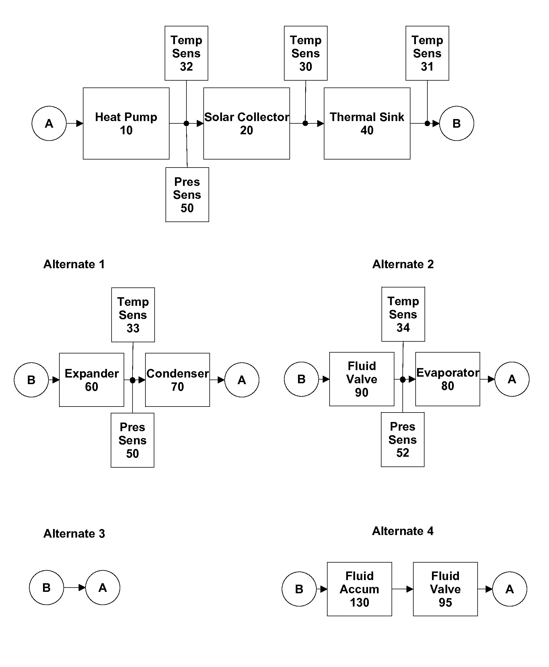
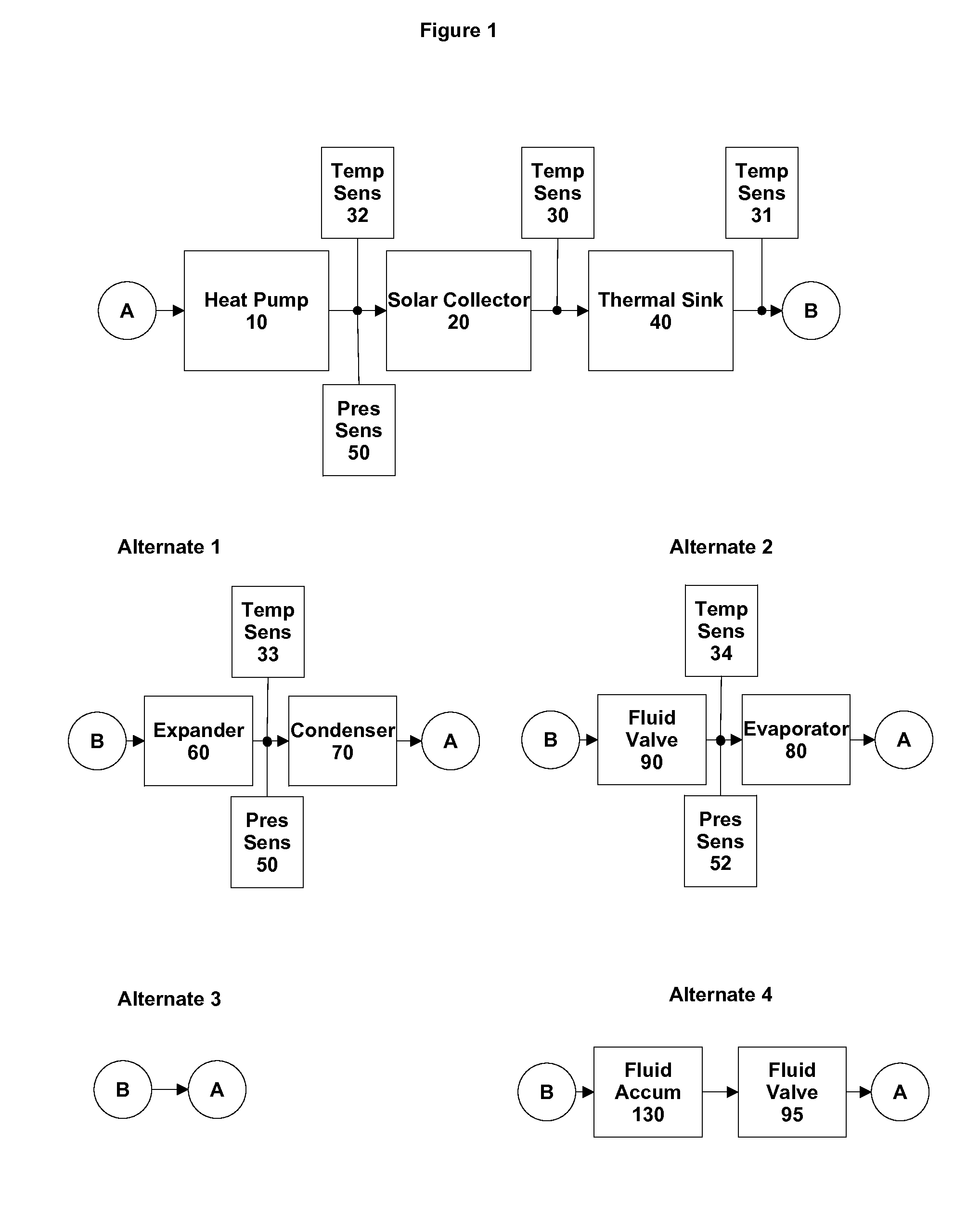
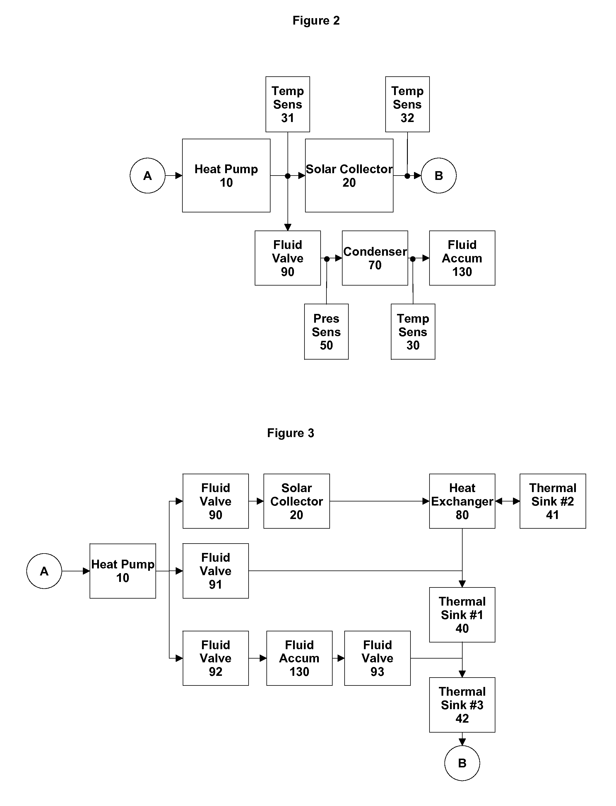

Image

  • Heat pump with intgeral solar collector
  • Heat pump with intgeral solar collector
  • Heat pump with intgeral solar collector

Examples


Embodiment Construction

[0026]The term “non-linear”, as used herein, includes any surface of a solar receiver whose surface shape is described by a set of nonlinear equations.

[0027]The term “microchannel”, as used herein, includes channel dimensions of less than 2.5 millimeters.

[0028]The term “reflector”, as used herein, includes a surface or surface coating that reflects greater than 50% of at least one portion of the incoming light spectrum, which includes the portions of visible, infrared, and ultraviolet.

[0029]The term “in thermal continuity” or “thermal communication”, as used herein, includes the direct connection between the heat source and the heat sink whether or not a thermal interface material is used.

[0030]The term “multipass”, “multi-pass”, or “multiple passes”, as used herein, includes a fluid flow into at least one portion of a heat exchanger and out of at least one other portion of a heat exchanger wherein the at least one portion of the heat exchanger and the at least one other portion of ...


PUM


Abstract

The present invention generally relates to heat pumps that utilize at least one thermal source operating with the same working fluids. In one embodiment, the present invention relates to a hybrid solar heat pump comprised of at least one microchannel heat exchanger with integral solar absorber, at least one compression (i.e., mass flow regulator) device as the heat pump for concurrent compression to a higher pressure and mass flow regulator of the working fluid, and at least one working fluid accumulator with the entire system operating with the same working fluid. The present invention also generally relates to heat pump systems that utilize an inventory management system to provide both efficient and safe operation under a wide range of operating conditions.

Description

CROSS-REFERENCE TO RELATED APPLICATIONS[0001]This application is a continuation-in-part of U.S. Patent Application Ser. No. 61,231,674 filed Aug. 6, 2009, having the title “Solar collector with expandable fluid mass management system” and U.S. Patent Application Ser. No. 61,231,238 filed Aug. 4, 2009, having the title “Heat Pump with Integral Solar Collector” and included as reference only without priority claims. Numerous additions have been made since the filing of the provisional patent applications cited earlier. These include FIGS. 9-14, and FIG. 17. The combining of the two provisional filings have lead to some of the original figures being renumbered to maintain like numerals for like components.FIELD OF THE INVENTION[0002]The present invention generally relates to a heat pump system having a highly integrated mass management system and external heat source to increase operating efficiency and reduce capital cost. In all embodiments, the present invention utilizes the same wo...

Claims


Application Information

Patent Timeline
Patent Type & Authority Applications(United States)
IPC IPC(8): F25B27/00F25D17/02F25B13/00
CPCF25B27/002Y02B10/24Y02B10/20Y02A30/272
Inventor GURIN, MICHAEL H.
Owner SOL XORCE
Learn More