

Two-Stroke Uniflow Turbo-Compound Internal Combustion Engine
a technology of internal combustion engine and turbo-compound, which is applied in the direction of internal combustion piston engine, combustion engine, machine/engine, etc., can solve the problems of almost entirely air remaining in the charge, large amount of stream, diesel engine problems, etc., and achieve the effect of increasing the turbulence of swirling scavenging air and high flow coefficien
Inactive Publication Date: 2011-02-10
TAYLOR PATENT HLDG CO LLC
View PDF26 Cites 18 Cited by
- Summary
- Abstract
- Description
- Claims
- Application Information
AI Technical Summary
Benefits of technology
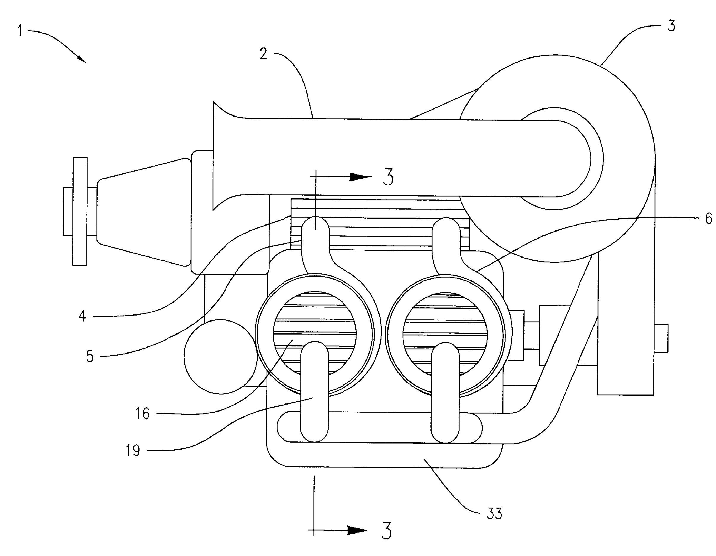
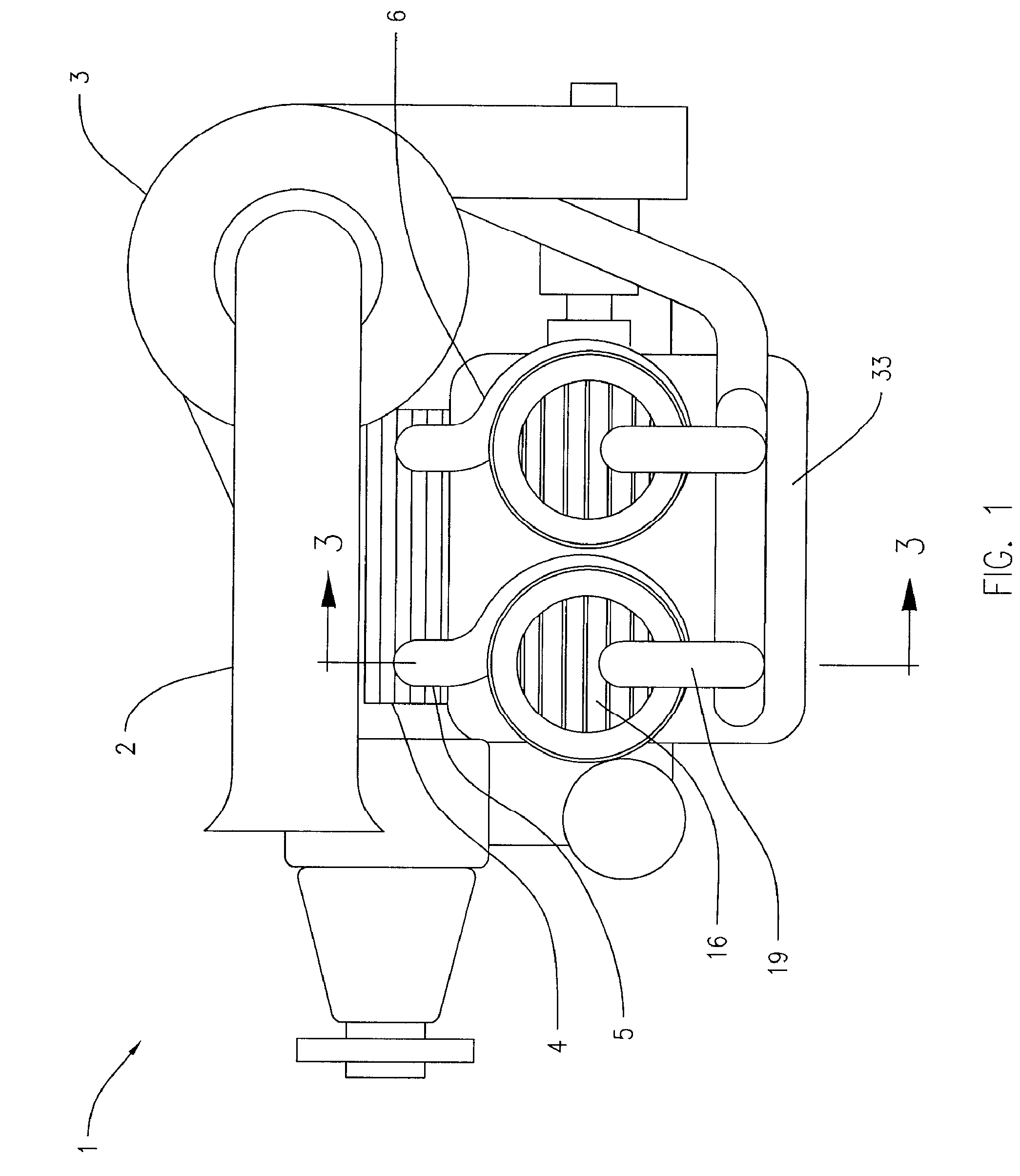
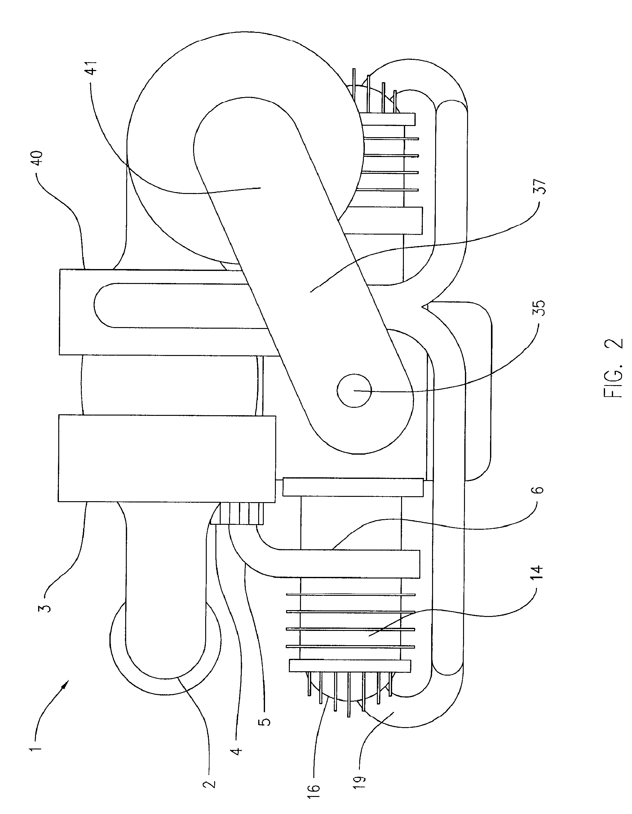
[0008]The present invention provides an improved cylinder design for a reciprocating two-stroke uniflow internal combustion (IC) engine, and for engines having multiple cylinders that provides improved swirling and turbulence of inlet air and mixing with fuel.
[0011]An aspect of the invention is to provide uniform, turbulent, upward inlet air swirling through the cylinder, which results in rapid, well defined, stratified charge combustion and very short combustion delay times.
[0015]Another aspect of the present invention is the improved cylinder design for the reciprocating two-stroke uniflow internal combustion (IC) engine using lean burning, direct fuel injection with high inlet air swirl and mixing with the fuel, and a spark ignition means. The lean burning reduces the flame temperature and combustion heat losses and NOx emissions.
[0016]Another aspect of the present invention is the use of thermal barrier treatments on the inside of the cylinders to further reduce combustion heat loss.
[0021]In another aspect of the invention, the lateral cross section of the scroll plenum reduces in area as it extends around the circumference of the cylinder wall, thereby maintaining the velocity of the air flowing through the air plenum and succeeding swirl ports progressing around the circumference of the cylinder wall. In another aspect of the invention, the cross sectional shape of a swirl port includes circular, oval, elliptical and polygonal, with streamlined flow passages to provide high flow coefficients and precisely directed flow.
[0022]In another aspect of the invention, the head of the piston includes a plurality of auxiliary vanes disposed on the crown and oriented in the radial direction from the center of the piston crown, transverse to the direction of the swirl vanes, to increase the turbulence of the swirling scavenging air upward within the cylinder chamber.
Problems solved by technology
The problem with this design is that after the combustion process is complete, the resulting exhaust stream contains a considerable amount of free single atoms of oxygen and nitrogen, the result of the heat of combustion splitting the O2 and N2 molecules in the air.
However the Diesel engine has problems as well.
This leads to portions of the charge remaining almost entirely air and others almost entirely of unburnt fuel lacking for oxygen.
This incomplete combustion leads to the presence of other pollutants such as partially burnt and unburnt fuel—polycyclic aromatic hydrocarbons and the plainly visible exhaust soot.
After years of trying, this layout has proven not to be terribly easy to arrange.
The system has been used for many years in slow-running industrial applications, but has generally failed to develop into an automobile engine.
Method used
View moreImage
Smart ImageViewing Examples

Examples
example 2
[0077]Published and calculated specifications for a conventional Rotax 912 engine, and calculations for a modified Rotax 912 turbocompound engine with the uniflow internal combustion cylinder of the present invention, are presented below in Table B:
TABLE BRotax 912Turbocompound(Published)(Calculated)(calculated)Horsepower8080.2500Displacement - cu. in.7475.961.6SFC - lb / hp-hr0.460.490.286
Login to View More PUM
 Abstract
A reciprocating two-stroke uniflow internal combustion (IC) cylinder and multiple cylinder engine, the cylinder having a cylinder wall and a cylinder head, the cylinder head having an exhaust port, a fuel injector, and a spark means disposed through the cylinder head, a piston reciprocally mounted in the cylinder for movement alternately through compression and power strokes, and a scroll plenum extending unidirectional around the outside of the cylinder wall and having an inlet and a plurality of swirl ports disposed through the cylinder wall providing fluid communication from the scroll plenum into the cylinder chamber, wherein the plurality of swirl ports enter the cylinder chamber tangentially with respect to the axial centerline of the cylinder, and wherein the plurality of swirl ports are subject to opening and closing in response to movement of said piston.
Description
CROSS-REFERENCE TO RELATED APPLICATION[0001]This application claims the benefit of U.S. Provisional Application No. 61 / 231,306, filed on Aug. 4, 2009, the disclosure of which is incorporated herein by reference.BACKGROUND OF THE INVENTION[0002]The stratified charge engine is a type of internal-combustion engine, similar in some ways to the Diesel cycle, but running on normal gasoline. The name refers to the layering of fuel / air mixture, the charge inside the cylinder. In a traditional Otto cycle engine the fuel and air arc mixed outside the cylinder and are drawn into it during the intake stroke. The air / fuel ratio is kept very close to stoichiometric, which is defined as the exact amount of air necessary for a complete combustion of the fuel. This mixture is easily ignited and burns smoothly. The problem with this design is that after the combustion process is complete, the resulting exhaust stream contains a considerable amount of free single atoms of oxygen and nitrogen, the resu...
Claims
Login to View More Application Information
Patent Timeline
 Patent Type & AuthorityApplications(United States)
IPC IPC(8): F02B31/00
CPCF01N5/04F02B25/04F02B29/0406F02B41/10F02B2075/025Y02T10/146Y02T10/163F02B31/04Y02T10/12
InventorTAYLOR, JACK R.
OwnerTAYLOR PATENT HLDG CO LLC