Transmission electron microscope and method for observing specimen image with the same

a transmission electron microscope and specimen technology, applied in the field of transmission electron microscope and a method for observing a specimen image with the same, can solve the problems of long time required for obtaining images, low time resolution, and difficulty in observing specimens from a plurality of directions at a time, and achieve the effect of improving the observation efficiency of an observer

Inactive Publication Date: 2011-02-10
HITACHI LTD
View PDF8 Cites 19 Cited by
  • Summary
  • Abstract
  • Description
  • Claims
  • Application Information

AI Technical Summary

Benefits of technology

[0016]An aspect of the present invention makes it possible to: obtain plural observed images simultaneously in an identical region of a specimen; double the obtained information capacity; and improve the observation efficiency of an observer. That is, two images corresponding to simultaneously obtained right and left visual field images are based on the image formation of two electron beams having transmitted a specimen at a completely identical time and simultaneous observation is strictly realized. Consequently, the same dynamic observation and real-time observation as ordinary electron microscopic observation comes to be possible only with being restricted by the time resolution of a specimen image in a detection system.

Problems solved by technology

In a conventional electron microscope, it has been difficult to observe a specimen from a plurality of directions at a time.
The above methods are inappropriate for dynamic observation and real-time observation however because, in any of the methods, a plurality of images are taken in sequence and thus the time required for obtaining the images is long.
That is, any of the methods requires image obtaining operations corresponding to the number of the images in order to obtain the plural images, the time resolution is low, and dynamic observation and real-time observation have not been successful.

Method used


Image

  • Transmission electron microscope and method for observing specimen image with the same
  • Transmission electron microscope and method for observing specimen image with the same
  • Transmission electron microscope and method for observing specimen image with the same

Examples


first embodiment

[0083]As a first embodiment according to the present invention, an example of a transmission electron microscope on which an optical system shown in FIG. 4 is mounted is shown in FIG. 12. In FIG. 12, an electron-optical system has: an electron source (or an electron gun) 1; an acceleration tube 40; a condenser optical system (a first condenser lens 41 and a second condenser lens 42); and an imaging optical system (an objective lens 5, a first imaging lens 61, a second imaging lens 62, a third imaging lens 63, and a fourth imaging lens 64). The electron-optical system is assembled in a vacuum chamber 18 and the vacuum chamber is continuously exhausted with a vacuum pump.

[0084]Further, the reference numeral 19 represents a control unit of the electron source, 49 a control unit of the acceleration tube, 48 a control unit of the first condenser lens, 96 a control unit of a first electron biprism, 47 a control unit of the second condenser lens, and 39 a control unit of a specimen 3 for c...

second embodiment

[0100]FIG. 14 shows an example of a transmission electron microscope on which an optical system shown in FIG. 8 is mounted. A condenser aperture 15 is disposed in the vicinity of the principal plane of a second irradiation lens 42 and a first electron biprism 91 is disposed on the upstream side of the condenser aperture 15. The reference numeral 17 represents a control unit to control the condenser aperture 15. The other part of the configuration is the same as the configuration shown in FIG. 12, but only one imaging unit 79 is installed. That is, one imaging unit 79 having a record area large enough to record two independent specimen images 321 and 323 is envisaged. In the case of the system, since only one reorder is used, unlike the case of the first embodiment, the sensitivity adjustment between imaging units (Steps 3 and 4 in FIG. 13) is not required. An output unit 76 is an example of a type of individually drawing two images 761 and 762.

[0101]In the present embodiment, in the...

third embodiment

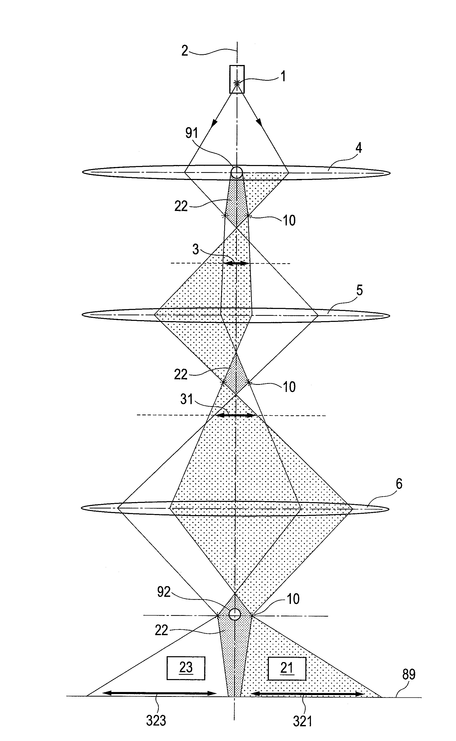
[0102]FIG. 15 shows an example of envisaging an interference type electron microscope that uses two electron biprisms in a condenser optical system shown in FIG. 9. In the condenser optical system, a third electron biprism 93 is disposed in a space 22 at the shadow of a first electron biprism 91, two electron beams 21 and 23 are deflected, and the same prescribed region of a specimen 3 is irradiated. The reference numeral 98 represents a control unit of the third electron biprism. With regard to an adjusting method of the optical system, in the flow shown in FIG. 13, processing on the third electron biprism 93 is added in addition to the processing on the first electron biprism 91 at steps 5 to 10.

[0103]By the configuration, Fresnel diffraction waves caused by the third electron biprism 93 do not appear. Other details are the same as Examples 1 and 2 described earlier. As an image output apparatus 76, for example, a stereoscopic monitor using a stereo viewer of a deflection type is ...


PUM


Abstract

A first electron biprism is disposed in a condenser optical system and an observation region of a specimen is irradiated simultaneously with two electron beams of different angles. The two electron beams that have simultaneously transmitted the specimen are spatially separated and focused with a second electron biprism disposed in an imaging optical system and two electron microscopic images of different irradiation angles are obtained. The two picture images are obtained by a detecting unit. Based on the two picture images, a stereoscopic image or two images having different kinds of information of the specimen is/are produced and displayed on a display device.

Description

CLAIM OF PRIORITY[0001]The present application claims priority from Japanese patent application JP 2009-184998 filed on Aug. 7, 2009, the content of which is hereby incorporated by reference into this application.FIELD OF THE INVENTION[0002]The present invention relates to a transmission electron microscope and a method for observing a specimen image with the transmission electron microscope.BACKGROUND OF THE INVENTION[0003]An electron beam has a strong interaction with a substance; and, in order to be used as a probe, must be accelerated at a high voltage and propagated in vacuum. For that reason: it is impossible to configure an optical system on an optical bench by using a three-dimensional space like a laser optical system; and the system is configured by one-dimensionally arraying a source (an electron source), a lens, a specimen, and an observation device in one vacuum chamber (one mirror body). Because of such a configuration, with a conventional electron microscope, it is ve...

Claims


Application Information

Patent Timeline
Patent Type & Authority Applications(United States)
IPC IPC(8): H01J37/26
CPCH01J37/28H01J2237/1514H01J37/295H01J2237/2614H01J2237/2611
Inventor HARADA, KENSUGAWARA, AKIRA
Owner HITACHI LTD
Why Eureka
Try Eureka