
Device for microscopy having selective illumination of a plane

a plane illumination and microscopy technology, applied in the field of microscopy devices, can solve the problems of reducing the efficiency of the microscopy process, affecting the quality of the microscopy, so as to reduce the stress of the sample and shorten the image recording time

Active Publication Date: 2011-02-10
CARL ZEISS MICROSCOPY GMBH
View PDF7 Cites 32 Cited by
  • Summary
  • Abstract
  • Description
  • Claims
  • Application Information

AI Technical Summary

Benefits of technology

The present invention is an improved microscopy device for imaging biological or non-biological objects using fluorescence light. The device uses a special technique called SPIM, which allows for the generation of optical sections through the use of a light sheet. The device has a detector that can acquire the emitted radiation from the object using a time-resolved method, which makes it possible to discriminate between different signal components. The device has a pulsed laser for excitation and can use a time-gated image intensifier or a time-resolved single photon counter for detection. The detector has a plurality of detector elements that emit time signals based on the acquisition time of photons. The device can acquire the decay curve of the fluorescence radiation of the object and can be used for imaging fluorescence lifetime microscopy methods. The technical effects of the invention include improved speed, reduced stressing of samples, and low bleaching of samples.

Problems solved by technology

However, the problem with raster scanning methods generally is that they are relatively time-consuming with typical image recording times in the range of seconds.
This results in problems with respect to the time expended on measurements.
Further, problems can arise with respect to possible bleaching processes in the fluorophores.
Another problem occurring in the known methods working in the frequency domain is the impossibility of an efficient discrimination of the excitation light or autofluorescence light of the object to be examined with respect to the fluorescence radiation of interest.
The objects to be examined are excited focally and afocally in this case, although only the focal excitation is actually used, so that there is a problem with excessive bleaching of fluorophores.

Method used


Image

  • Device for microscopy having selective illumination of a plane
  • Device for microscopy having selective illumination of a plane
  • Device for microscopy having selective illumination of a plane

Examples


Embodiment Construction

[0023]It is to be understood that the figures and descriptions of the present invention have been simplified to illustrate elements that are relevant for a clear understanding of the present invention, while eliminating, for purposes of clarity, many other elements which are conventional in this art. Those of ordinary skill in the art will recognize that other elements are desirable for implementing the present invention. However, because such elements are well known in the art, and because they do not facilitate a better understanding of the present invention, a discussion of such elements is not provided herein.

[0024]The present invention will now be described in detail on the basis of exemplary embodiments.

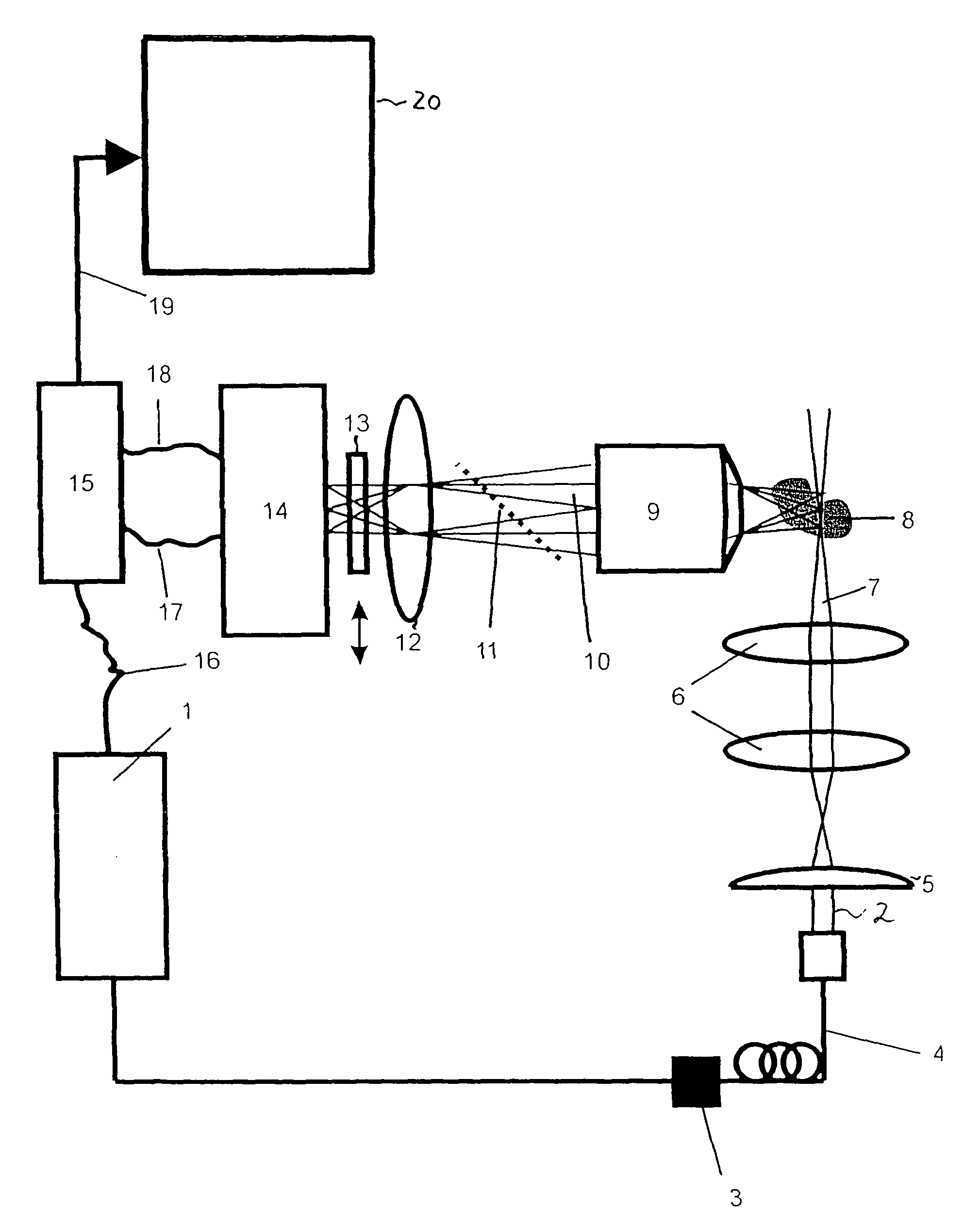
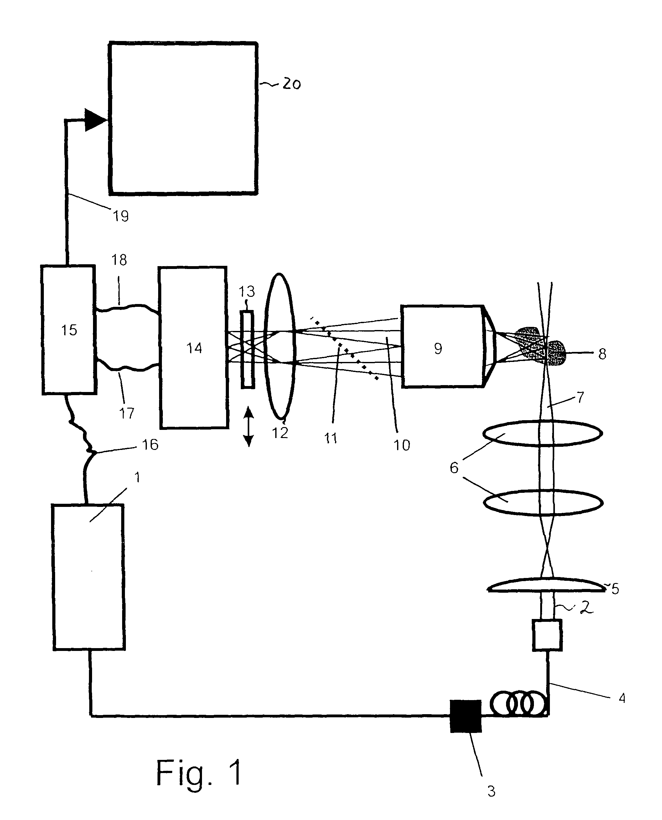
[0025]FIG. 1 is a schematic diagram showing a microscopy device according to an embodiment example of the invention. The microscopy device is designed for use in imaging fluorescence lifetime microscopy methods in the time domain in which the generation of optical sections by t...


PUM


Abstract

A microscopy device, particularly for use in an imaging fluorescence lifetime microscopy method is provided. The microscopy device comprises an illumination means for generating an illumination beam, an imaging detector for spatially resolved acquisition of an emission radiation emitted by an object to be examined, an illumination beam path between the illumination means and the object to be examined, and a detection beam path between the object to be examined and the detector. The illumination beam path comprises illumination optics which are designed to generate a light sheet of illumination radiation extending transverse to the axis of the illumination beam path, wherein the axis of the detection beam path is oriented substantially perpendicular to a section plane of the light sheet and of the object to be examined. The illumination means comprise a pulsed laser.

Description

[0001]The present application claims priority from PCT Patent Application No. PCT / EP2009 / 002504 filed on Apr. 4, 2009, which claims priority from German Patent Application No. DE 10 2008 018 476.4 filed on Apr. 11, 2008, the disclosure of which is incorporated herein by reference in its entirety.BACKGROUND OF THE INVENTION[0002]1. Field of the Invention[0003]The present invention is directed to a microscopy device, in particular a microscopy device for the imaging acquisition of fluorescent light.[0004]2. Description of Related Art[0005]It is known in the field of microscopy to use fluorescent light when generating two-dimensional or three-dimensional images of an object to be examined, e.g., a biological sample. In so doing, the fluorescence intensity in particular can be detected. Further, it is possible to use the individual fluorescence lifetimes of fluorophores to generate contrasts. This latter procedure is known as FLIM (Fluorescence Lifetime Imaging Microscopy). The fluoresc...

Claims


Application Information

Patent Timeline
Patent Type & Authority Applications(United States)
IPC IPC(8): G01J1/58
CPCG02B21/002G02B21/10G02B21/06G02B21/16
Inventor LIPPERT, HELMUTPOWER, CHRISTOPHERDIETRICH, CHRISTIANRADT, BENNO
Owner CARL ZEISS MICROSCOPY GMBH
Learn More