The differential vco and quadrature vco using center-tapped cross-coupling of transformer

Inactive Publication Date: 2011-02-10
ELECTRONICS & TELECOMM RES INST
View PDF17 Cites 23 Cited by
  • Summary
  • Abstract
  • Description
  • Claims
  • Application Information

AI Technical Summary

Benefits of technology

[0019]First, the differential VCO and the quadrature VCO according to the present invention can be driven by low power through the current reuse structure.
[0020]Second, the differential VCO and the quadrature VCO according to the present invention have an excellent phase noise characteristic by center-tapped cross-coupling through the transformer.
[0021]Third, in the differential VCO and the quadrature VCO according to the present invention, the variable capacitance units for frequency variation are divided into variable capacitance units for coarse tuning and variable capacitance units for fine tuning. Therefore, it is possible to obtain a wide tuning range whi

Problems solved by technology

In the LC VCO 100, however, since the NMOS transistor NM and the PMOS transistor PM are not exactly symmetrical with each other, an output is unbalanced.
Meanwhile, when a quadrature VCO is

Method used


Image

  • The differential vco and quadrature vco using center-tapped cross-coupling of transformer
  • The differential vco and quadrature vco using center-tapped cross-coupling of transformer
  • The differential vco and quadrature vco using center-tapped cross-coupling of transformer

Examples


Example

[0033]Hereinafter, exemplary embodiments of the present invention will be described in detail with reference to the accompanying drawings.

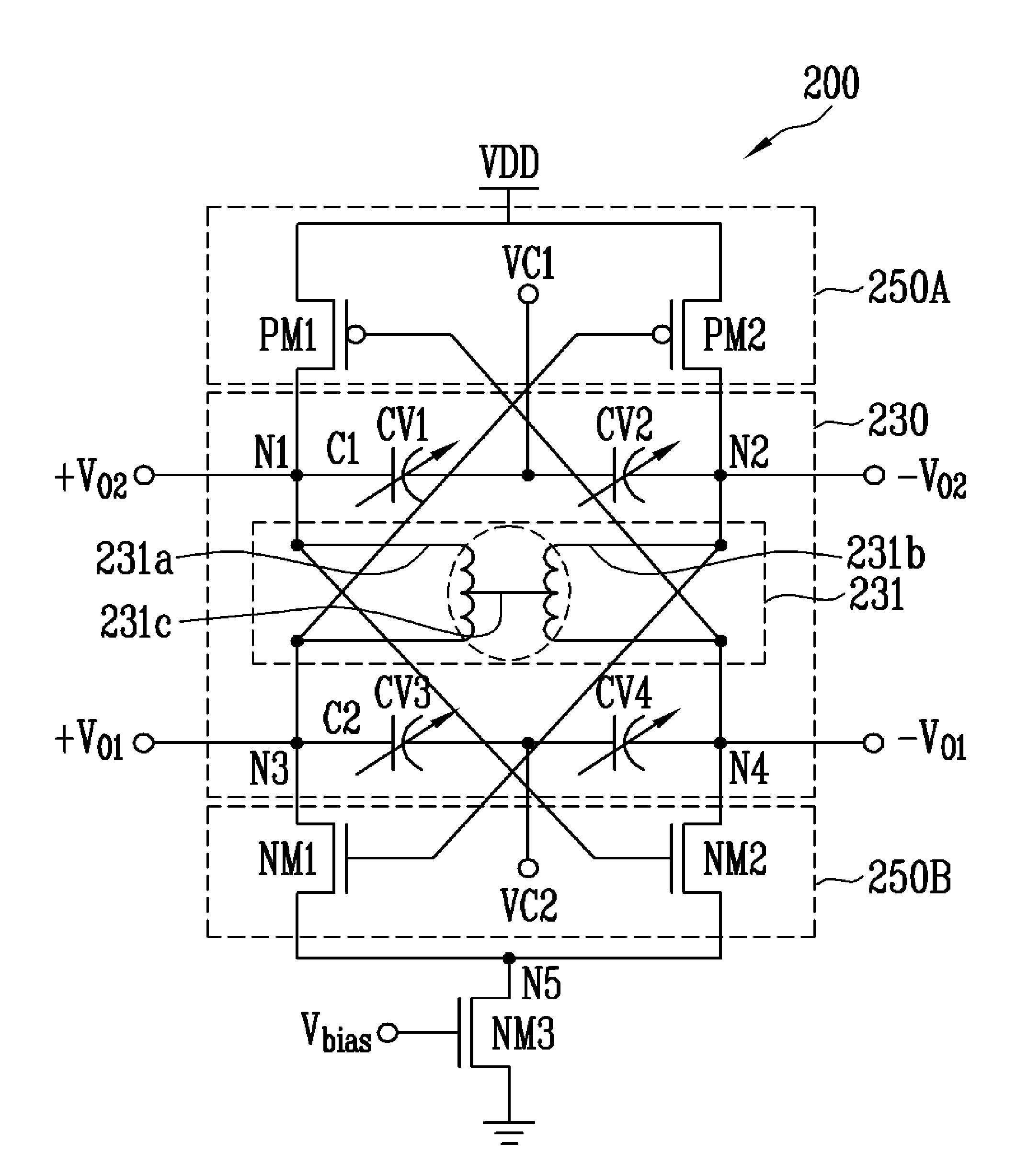
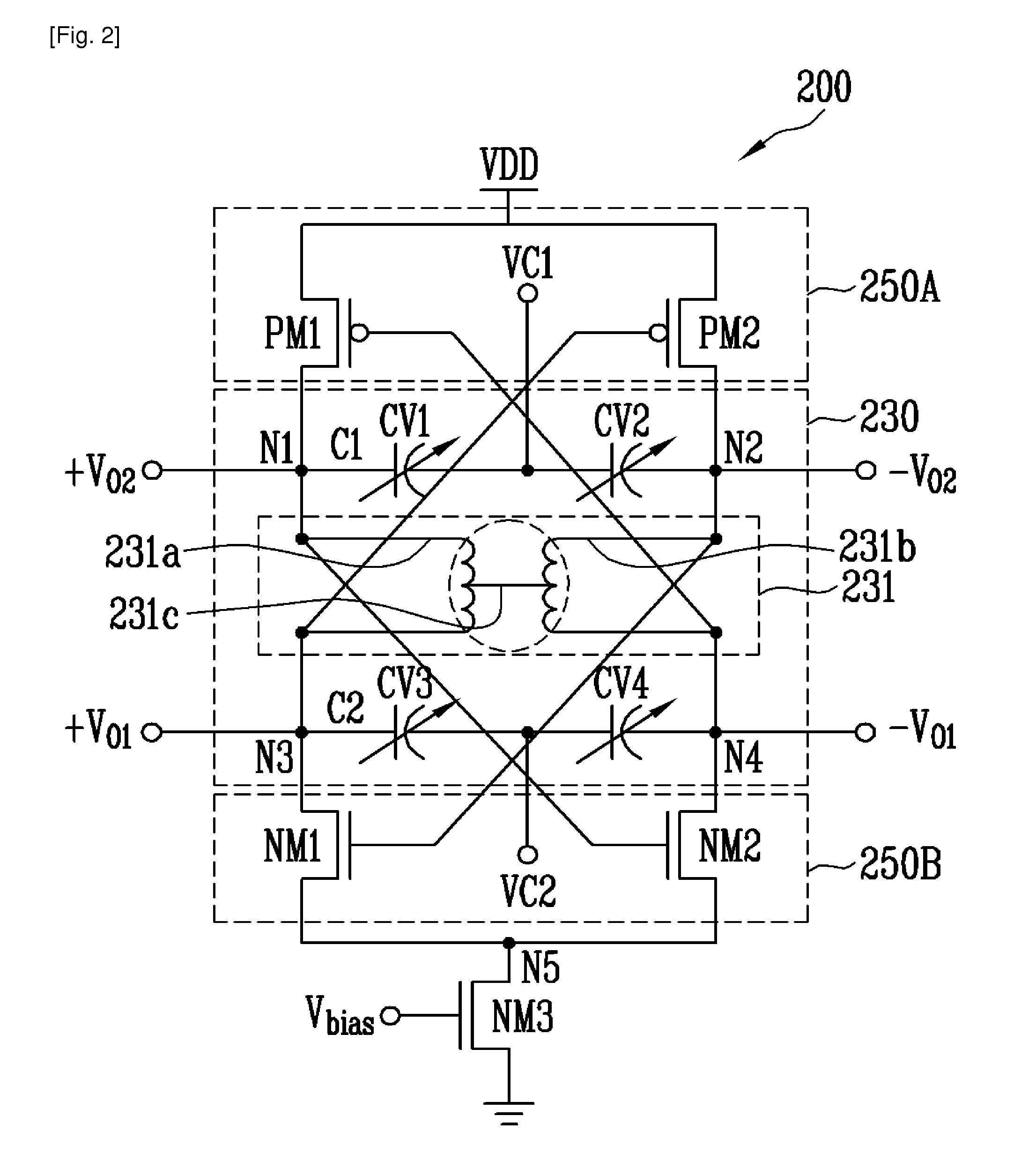
[0034]FIG. 2 is a circuit diagram of a differential VCO according to the present invention.

[0035]Referring to FIG. 2, the VCO 200 according to the present invention includes a resonant circuit 230 which oscillates a frequency depending on first and second control voltages VC1 and VC2 and first and second amplification circuits 250A and 250B which differentially amplify the oscillation frequency output from the resonant circuit 230.

[0036]The first amplification circuit 250A includes first and second PMOS transistors PM1 and PM2, the second amplification circuit 250B includes first and second NMOS transistors NM1 and NM2, and the resonant circuit 230 includes a transformer 231 and first to fourth variable capacitance units CV1 and CV4 connected to the transformer 231.

[0037]The connections among the components will be described in detail as follows.

[...


PUM


Abstract

Provided are a differential voltage-controlled oscillator (VCO) and a quadrature VCO using center-tapped cross-coupling of a transformer. The differential VCO and the quadrature VCO can be driven by low power through a current reuse structure and have an excellent phase noise characteristic by center-tapped cross-coupling through a transformer. Further, variable capacitance units for frequency variation are divided into variable capacitance units for coarse tuning and variable capacitance units for fine tuning. Therefore, it is possible to obtain a wide tuning range while voltage oscillation gain is reduced. Further, the differential VCO and the quadrature VCO are configured in such a manner that the respective variable capacitance units operate linearly throughout the entire capacitance region due to control voltage distribution by resistors. Accordingly, it is possible to obtain a linear control voltage-oscillation frequency characteristic. The quadrature VCO according to the present invention can output four-phase quadrature signals while having an excellent phase noise characteristic, without substrate loss and current consumption caused by the switching transistors.

Description

TECHNICAL FIELD[0001]The present invention relates to a differential voltage-controlled oscillator (VCO) and a quadrature VCO using center-tapped cross-coupling of a transformer, and more specifically, a VCO which exhibits low-power and excellent phase noise characteristics by using center-tapped cross-coupling of a transformer, and has a wide oscillation frequency range and a linear control voltage-oscillation frequency characteristic.[0002]This work was supported by the IT R&D program of MIC / IITA [2006-S-070-02, Development of Cognitive Wireless Home Networking System].BACKGROUND ART[0003]In general, a VCO is an oscillator with a variable capacitor whose capacitance is changed through voltage adjustment, to thereby adjust the frequency. Such a VCO is an essential component of all electrical communication systems and may be used for up-converting or down-converting a frequency of a predetermined signal.[0004]FIG. 1 is a circuit diagram of a conventional LC VCO.[0005]Referring to FI...

Claims


Application Information

Patent Timeline
IPC IPC(8): H03B5/12
CPCH03B5/1228H03B5/1296H03B5/1243H03B5/1212H03B5/12
Inventor LEE, YOUNG JAEKIM, CHEON SOO
Owner ELECTRONICS & TELECOMM RES INST
Why Eureka
Try Eureka