Assembly for a stator stage of a turbomachine, the assembly comprising an outer shroud and at least one stationary vane

a stator stage and assembly technology, applied in the direction of wind motors, liquid fuel engines, wind turbines with parallel air flow, etc., can solve the problems of thread breaking risk, corresponding fabrication costs, and weigh

Inactive Publication Date: 2011-02-10
TECHSPACE AERO
View PDF9 Cites 20 Cited by
  • Summary
  • Abstract
  • Description
  • Claims
  • Application Information

AI Technical Summary

Benefits of technology

[0019]An object of the present invention is to provide a solution enabling the drawbacks of the prior art to be overcome, and in particular making it possible to avoid encountering the above-mentioned problems inherent to screw-thread fastener techniques or to implementing welding through the entire thickness of the outer shroud.
[0029]In this way, since the outline of the outer segment of an opening in the outer shroud is offset, in radial projection, around the outline of the inner segment of the same opening, the welding operation performed all around the outline of the outer segment does not affect the vane thermally. In this way, no droplets of material are formed in the air-flow section.
[0030]This solution also presents the supplementary advantage of making it possible, additionally, to avoid using a specific part known as a “beam stopper” that is usually used to prevent the welding beam thermally affecting the remainder of the vane. In the invention, it is the zone of the inside wall of the outer shroud lying between the two openings that performs this function.
[0032]Overall, by means of the solution of the present invention, it is possible to avoid the presence of a weld bead or of droplets of welding within the air-flow section.
[0033]Overall, by means of the solution of the present invention, it is possible to position each stationary vane reliably relative to the shroud.

Problems solved by technology

Nevertheless, there exist certain drawbacks if a threaded bolt is used at the top of a vane and penetrates into an opening in the shroud, where it is held by a nut screwed onto the outside of the shroud.
The presence of a screw thread leads to the risk of the thread breaking, there are corresponding fabrication costs, and account needs to be taken of the weight of the nut.
In addition, other problems are encountered when using known techniques for mounting by welding.
However, in order to achieve the required strength, it is necessary for the welding that connects the shroud to an end portion of the top of the vane to be performed through the entire thickness of the material of the outer shroud, which, given the welding techniques that can be implemented, necessarily gives rise to a melt bath through the entire thickness of the material of the shroud, thereby giving rise to droplets of material being spattered on the inside face of the shroud, and thus in the air-flow section.
It will be understood that such welding through the entire thickness gives rise to drawbacks, including the following:deformation of the welded parts, and in particular of the outer shroud;spattering of droplets of material giving rise, together with the weld bead, to surface discontinuities in the inside face of the outer shroud, thereby disturbing the stream and generating head loss in the air-flow section, such that in order to remove these surface discontinuities it is necessary to take further action on the assembly made up of the outer shroud and the welded stationary vanes, which action is complex and gives rise to additional fabrication costs, and can also give rise to other mechanical defects on those parts;strict fabrication tolerances are necessary for complying with the dimensions and the positioning of the openings in the outer shroud; andfabrication difficulties associated with the complex shape of the end portions of the tops of the vanes and the openings in the outer shroud, with this arising either during the machining of these elements or during the step of welding them together.

Method used


Image

  • Assembly for a stator stage of a turbomachine, the assembly comprising an outer shroud and at least one stationary vane
  • Assembly for a stator stage of a turbomachine, the assembly comprising an outer shroud and at least one stationary vane
  • Assembly for a stator stage of a turbomachine, the assembly comprising an outer shroud and at least one stationary vane

Examples


first embodiment

[0047]Reference is made initially to FIGS. 2 to 5 which relate to the invention.

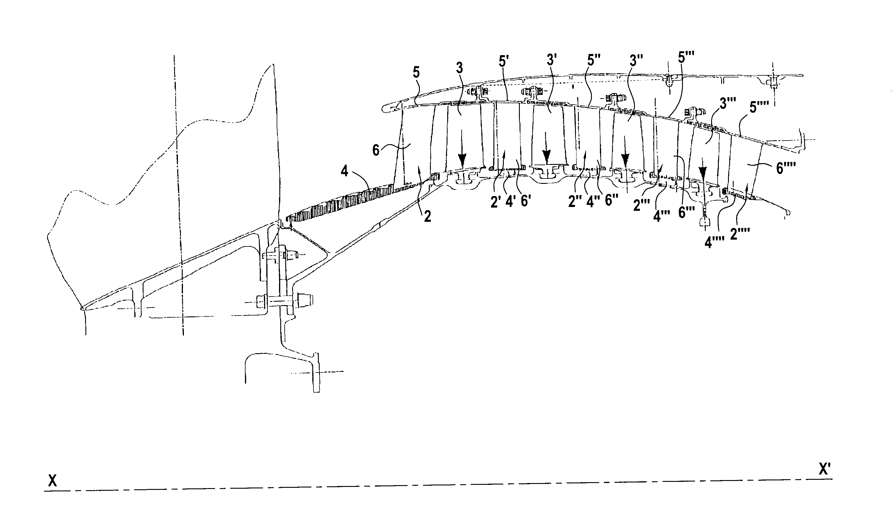
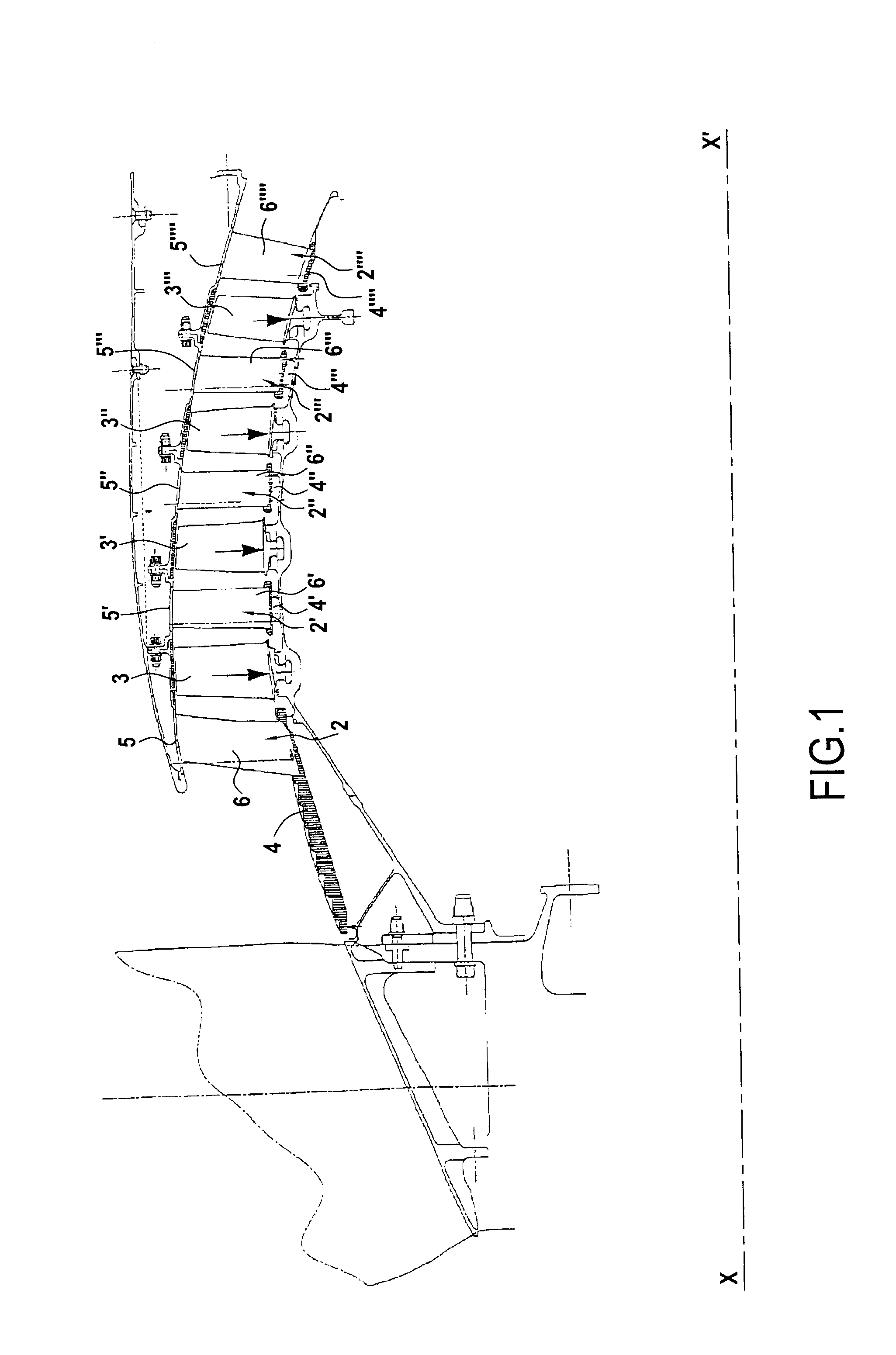
[0048]Like all of the stationary vanes making up the stator stage 2 under consideration, the vane 6 is connected via its root to the inner shroud 4 and via its top 62 to the outer shroud 5, the body 61 of the vane extending between the root and the top 62.

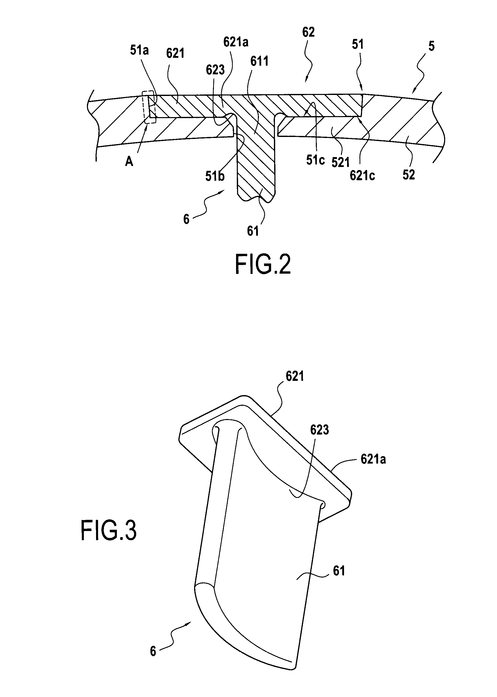
[0049]At the top 62, the body 61 of the vane is extended by a platform 621 via a connection zone 623 in the form of a connecting radius. The mean planes of the platform 621 and of the body 61 are mutually orthogonal.

[0050]As can be seen in FIGS. 3 and 4, the outline of the platform 621 presents the shape of a quadrilateral, more precisely of a parallelogram, and in particular of a rectangle of length that extends parallel to the width of the body 61 of the vane and of width that extends perpendicularly to the axial direction X-X′ of the shroud 5 (or of the turbomachine).

[0051]The variant of FIG. 5, the outline of the platform 621 is in the shape of a ki...

second embodiment

[0073]The inner segment 51b of the opening 51 defines a passage that receives the corresponding engagement portion of the vane as constituted in this second embodiment by the inner portion 621b of the platform 621.

[0074]The welded connection is still made between the outline of the outer segment 51a of the opening 51 and the outline of the outer portion 621a of the platform 621. Under such circumstances, the inner portion 621b of the platform 621 is merely housed without any particular connection in the inner segment 51b of the opening 51, with the inside face 621c of the outer portion 621a bearing against the bearing face 51c of the inside wall zone 52 of the shroud.

[0075]As in the first embodiment, it will be understood that this arrangement makes it possible to avoid thermally affecting the top of the vane 6 and the top of its airfoil.

[0076]In addition, in the second embodiment, it is necessary to adapt the outline of the inner segment 51b of the opening 51 to the shape of the ou...


PUM


Abstract

The invention relates to an assembly for a stator stage of a turbomachine, the assembly comprising:an outer shroud presenting a series of openings for mounting each stationary vane by welding between the edge of an opening and the outline of the platform of the vane, the outline of the outer segment of an opening surrounding, in radial projection, the outline of the inner segment thereof, the shroud not having any other holes; andat least one stationary vane with its top including a non-pierced platform received in one of said openings prior to the welding step, such that an inside face of the platform bears against a bearing face of the shroud, the outline of the platform presenting a shape that is identical to the shape of the outline of the opening.The invention is applicable to the stator stage of an axial compressor or a turbine of a turbomachine.

Description

FIELD OF THE INVENTION[0001]The invention relates to a stationary vane and the outer shroud of a stator stage of a turbomachine such as a turbojet or a turboprop, the shroud forming a casing that supports a plurality of series of stationary vanes having series of blades disposed therebetween, which blades are movable in rotation about a longitudinal axis, in particular for an axial compressor or a turbine used in an aviation turbojet.[0002]In the present specification, the axis X-X′ of rotation of the rotor of the turbomachine is referred to as the axis of the turbomachine and it also constitutes an axis of circular symmetry for the shroud and the stator stage. The axial direction corresponds to the direction of the turbomachine axis and a radial direction is a direction perpendicular to said axis. Likewise, an axial plane is a plane containing the turbomachine axis, a transverse plane is a plane perpendicular to said axis, and a radial plane is a plane perpendicular to the other tw...

Claims


Application Information

Patent Timeline
Patent Type & Authority Applications(United States)
IPC IPC(8): F04D29/40
CPCF05D2230/232F01D9/044
Inventor TURI, GABRIELBIEMAR, GUY
Owner TECHSPACE AERO
Why Eureka
Try Eureka