Implantable medical device lead incorporating a conductive sheath surrounding insulated coils to reduce lead heating during MRI

a medical device and lead technology, applied in the field of lead for use with implantable medical devices, can solve the problems of joule heating in cardiac tissues around the electrodes of lead electrodes, potential damage to adjacent tissues, and damage to myocardial tissue, so as to reduce the electrical coupling of enclosed conductors, reduce or eliminate shunt capacitance, and reduce the effect of electromagnetic coupling

Inactive Publication Date: 2011-02-10
PACESETTER INC
View PDF35 Cites 42 Cited by
  • Summary
  • Abstract
  • Description
  • Claims
  • Application Information

AI Technical Summary

Benefits of technology

[0014]The conducting sheath may be, for example, a metal mesh or a conducting polymer tube including non-ferrous metal powders. The sheath may be formed along at least a proximal portion of the lead or, preferably, along substantially its entire length. The insulated coil portion of the conductor may be formed, for example, along the entire length of the lead (continuously or in segments), or at its distal end, or at both the distal end and the proximal end of the lead. These are just some examples. By providing a conducting sheath along all or at least part of the lead, shielding of (and / or suppression of) induced currents is achieved so as to reduce electromagnetic coupling into enclosed conductors. In some examples, the conductive sheath is sub-divided into ¼ wavelength segments distributed along the entire length of the lead. By providing a conductive sheath with segments of about ¼ wavelength along the entire lead, it is believed that the induced currents from RF fields are greatly suppressed so that relatively little current can flow along the conductors enclosed by the sheath, therefore reducing heating at tip and ring electrodes. Moreover, by providing a conducting sheath around at least the proximal portion of the lead, shielding is provided to help reduce or counteract the aforementioned “coiling effect.” In particular, the conductive sheath may help to reduce or eliminate shunt capacitance between the insulated coil portion of the conductor and any external conducting structures, such as the housing of the implantable device. It is believed that reducing or eliminating the shunt capacitance has the effect, depending upon the relative proximity of the external conducting structures, of reducing heating within the lead due to strong RF fields, at least as compared to unshielded leads.
[0015]In an illustrative embodiment, wherein the lead is for use with a pacemaker or ICD, the lead is a co-axial bipolar lead having an inner conductor leading to a tip electrode at a distal end of the lead and also having an outer ring conductor leading to a ring electrode at the distal end of the lead. Both the inner and outer conductors are formed as insulated coils to function as inductive bandstop filters at RF signal frequencies. The conducting sheath generally extends along the entire lead length but is formed of several sections or segments. Each section or segment is preferred to be about ¼ wavelength (based on the wavelengths of current flowing in lead conductors in the presence of MRI RF fields or other strong magnetic fields.) Alternatively, the conducting sheath extends along just the proximal end of the lead, particularly along those portions of the lead that might be wrapped around or under the pacemaker or ICD. As such, the conducting sheath helps prevent shunt capacitance between the proximal end of the outer (i.e. ring) insulated conducting coil of the lead and the housing of the pacemaker or ICD.

Problems solved by technology

However, MRI procedures are problematic for patients with implantable medical devices such as pacemakers and ICDs.
One of the significant problems or risks is that the strong RF fields of the MRI can induce currents through the lead system of the implantable device into the tissues, resulting in Joule heating in the cardiac tissues around the electrodes of leads and potentially damaging adjacent tissues.
Although such a dramatic increase is probably unlikely within a clinical system wherein leads are properly implanted, even a temperature increase of only about 8°-13° C. might cause myocardial tissue damage.
Furthermore, any significant heating of cardiac tissues near lead electrodes can affect the pacing and sensing parameters associated with the tissues near the electrode, thus potentially preventing pacing pulses from being properly captured within the heart of the patient and / or preventing intrinsic electrical events from being properly sensed by the device.
The latter might result, depending upon the circumstances, in therapy being improperly delivered or improperly withheld.
Another significant concern is that any currents induced in the lead system can potentially generate voltages within cardiac tissue comparable in amplitude and duration to stimulation pulses and hence might trigger unwanted contractions of heart tissue.
The rate of such contractions can be extremely high, posing significant clinical risks to patients.
In particular, it has been found that any coiling of excess lead length by the clinician during device implant can affect the amount of heat reduction achieved using RF filtering elements.
It has been found that this can negate the efficacy of heat reduction features in leads, in some cases resulting in an increase of over 30 degrees Celsius (C) as compared to leads not coiled around or under the device.
Coiling a lead around or under a device appears to add a shunt capacitance to the coiled portion of the lead due to proximity with the metallic case of the device, which adversely affects the resulting L, Cs and Rs values and reduces the impedance and hence allows for greater unwanted heating during MRIs.

Method used


Image

  • Implantable medical device lead incorporating a conductive sheath surrounding insulated coils to reduce lead heating during MRI
  • Implantable medical device lead incorporating a conductive sheath surrounding insulated coils to reduce lead heating during MRI
  • Implantable medical device lead incorporating a conductive sheath surrounding insulated coils to reduce lead heating during MRI

Examples


Embodiment Construction

[0026]The following description includes the best mode presently contemplated for practicing the invention. The description is not to be taken in a limiting sense but is made merely to describe general principles of the invention. The scope of the invention should be ascertained with reference to the issued claims. In the description of the invention that follows, like numerals or reference designators will be used to refer to like parts or elements throughout.

Overview of MRI System

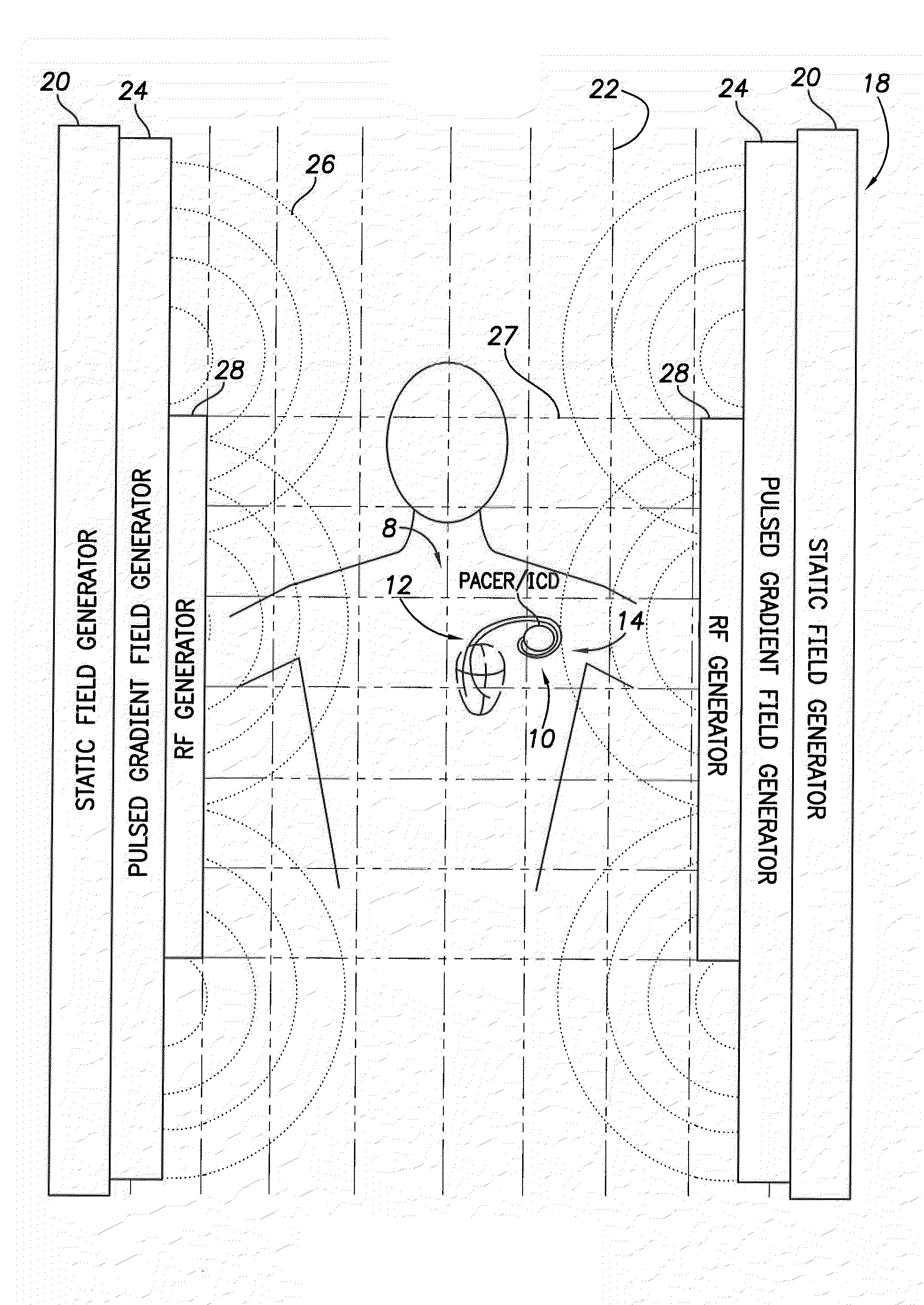
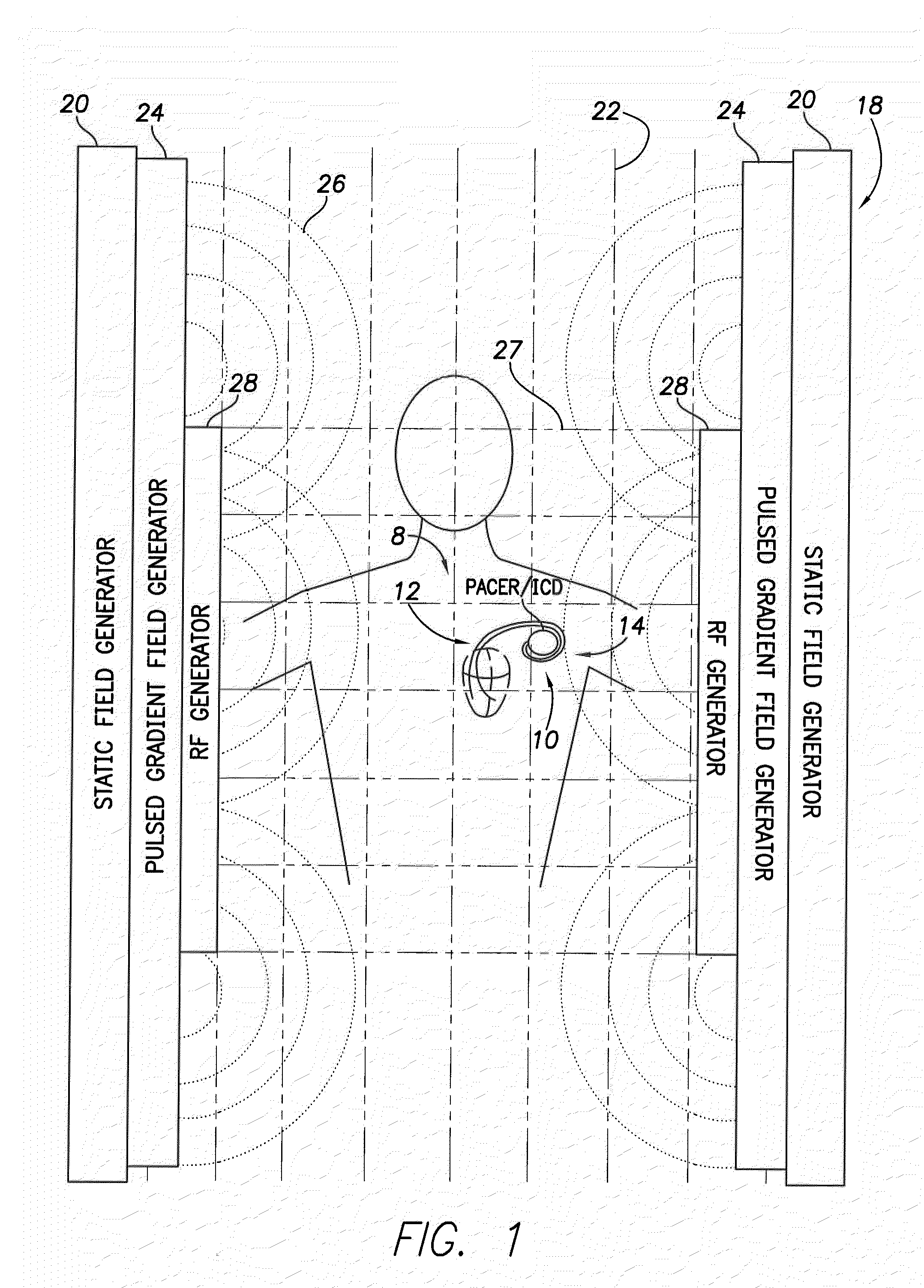
[0027]FIG. 1 illustrates an implantable medical system 8 having a pacer / ICD 10 for use with a set of bipolar pacing / sensing leads 12. In the example, proximal portions 14 of the leads have been wrapped around the pacer / ICD, as can occur if the clinician chooses to wrap excess portions of the lead around or under the device during device implant. As explained, the coiling of the lead around or under the pacer / ICD by the clinician can adversely affect heat reduction achieved by insulated coil bandstop filte...


PUM


Abstract

A conducting sheath is provided along at least a portion of an implantable medical device lead, and preferably along substantially its entire length, for mitigating heating problems arising during magnetic resonance imaging (MRI) procedures, particularly problems arising due to a problem described herein as the “coiling effect.” During device implant, the clinician may elect to wrap or coil excess proximal portions of leads around or under the medical device being implanted. Thereafter, during MRI procedures, shunt capacitance may develop between the housing of the implantable device and insulated coils within the proximal portions of the lead that are near the device, resulting in greater lead heating during the MRI. The conducting sheath helps suppress induced currents and also reduces or eliminates shunt capacitance. The conducting sheath may be, for example, formed using a metal mesh or a conducting polymer tube incorporating non-ferrous metal powders. The sheath may be formed in ¼ wavelength segments.

Description

CROSS-REFERENCE TO RELATED APPLICATIONS[0001]This application is related to U.S. patent application Ser. No. ______, filed concurrently herewith, titled “Implantable Medical Device Lead Incorporating Insulated Coils Formed as Inductive Bandstop Filters to Reduce Lead Heating During MRI” (Attorney Docket A09P1042), which is incorporated by reference herein in its entirety.FIELD OF THE INVENTION[0002]The invention generally relates to leads for use with implantable medical devices, such as pacemakers or implantable cardioverter-defibrillators (ICDs) and, in particular, to components for use within such leads to reduce heating during magnetic resonance imaging (MRI) procedures.BACKGROUND OF THE INVENTION[0003]MRI is an effective, non-invasive magnetic imaging technique for generating sharp images of the internal anatomy of the human body, which provides an efficient means for diagnosing disorders such as neurological and cardiac abnormalities and for spotting tumors and the like. Brief...

Claims


Application Information

Patent Timeline
Patent Type & Authority Applications(United States)
IPC IPC(8): A61N1/05
CPCA61N1/0563A61N2001/086A61N1/086
Inventor MIN, XIAOYIVIOHL, INGMAR
Owner PACESETTER INC
Why Eureka
Try Eureka