Converter control method

a technology of converter/inverter and control method, which is applied in the direction of electric generator control, dynamo-electric converter control, dynamo-electric gear control, etc., can solve the problems of deteriorating efficiency of the converting device as a whole of the converter/inverter, and achieve the effect of suppressing size and manufacturing costs, easy control of dc voltage, and improving the power factor of input power

Inactive Publication Date: 2011-02-17
DAIKIN IND LTD
View PDF10 Cites 10 Cited by
  • Summary
  • Abstract
  • Description
  • Claims
  • Application Information

AI Technical Summary

Benefits of technology

[0020]In the first aspect of the converter control method according to the present invention, a power supply phase of the multi-phase power source is required, but a voltage of the multi-phase power source is not required. Therefore, a circuit configuration for detecting a voltage of the multi-phase power source is not necessary, which makes it easy to control the DC voltage so as to improve a power factor of input power while suppressing the size and manufacturing costs.
[0021]In the second aspect of the converter control method according to the present invention, a time delay element such as the integral element is not included in the determination of the DC voltage command value. Accordingly, this determination is not delayed due to an instantaneous stop / recovery. Thus, occurrence of an overshoot of the DC voltage based on this delay can be avoided.
[0022]In the third aspect of the converter control method according to the present invention, the DC voltage can be set in accordance with driving of a load of the inverter. Therefore, an operating range of the inverter can be expanded.
[0023]In the fourth aspect of the converter control method according to the present invention, a primary delay element and the filter process such as an average computation are included in the determination of the DC voltage command value, and thereby a response of a control system which determines the DC voltage command value is made later than a response of a control system which determines the first voltage command value and the second voltage command value, so that a control which is stable with respect to a transient response is performed.

Problems solved by technology

This increases the loss of switching elements included in the converter and the inverter and the loss of a reactor interposed between the AC power source and the converter, which causes a problem that the efficiency of a converting device as a whole of a converter / inverter deteriorates.

Method used


Image

  • Converter control method
  • Converter control method
  • Converter control method

Examples


first embodiment

(b-2) Converter Control Method

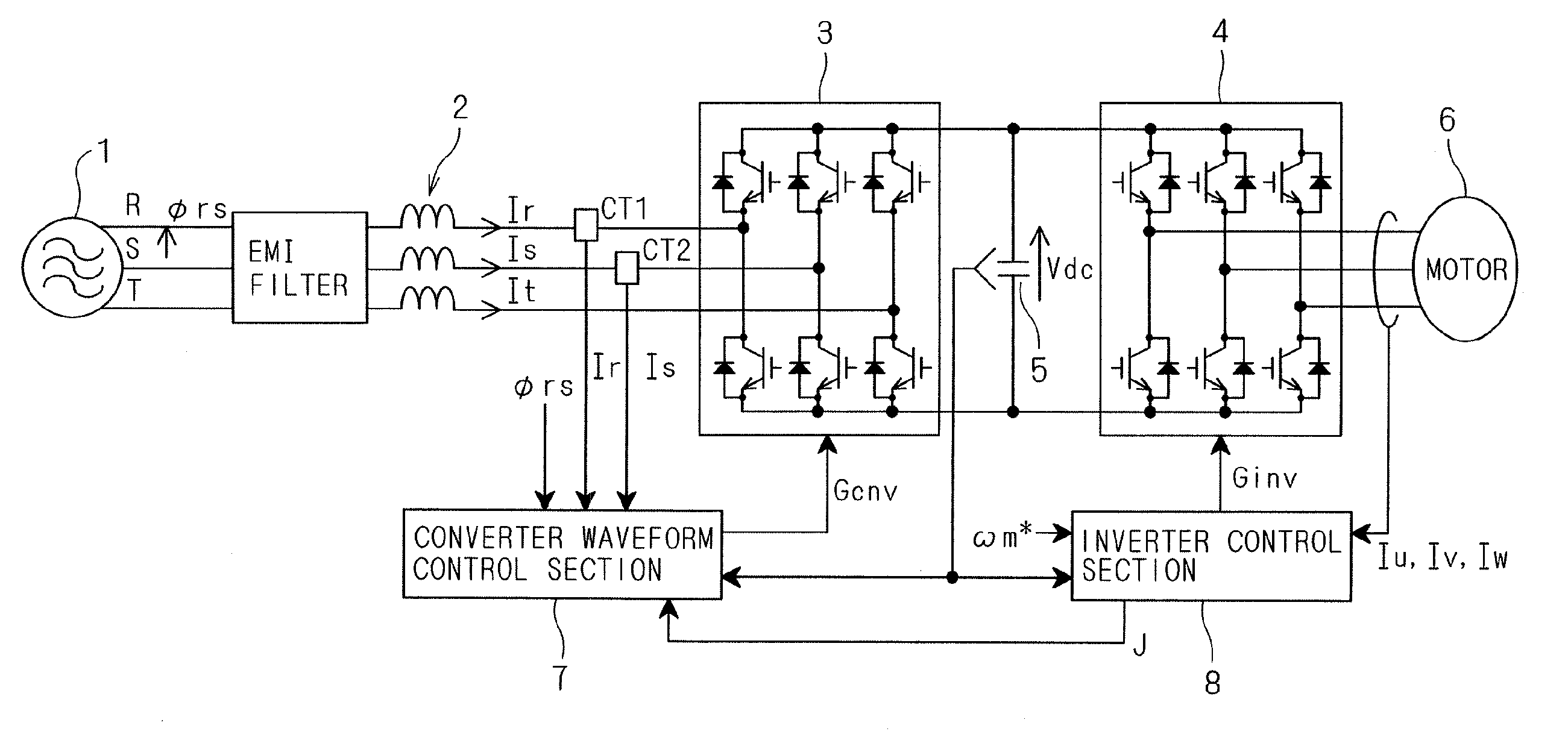
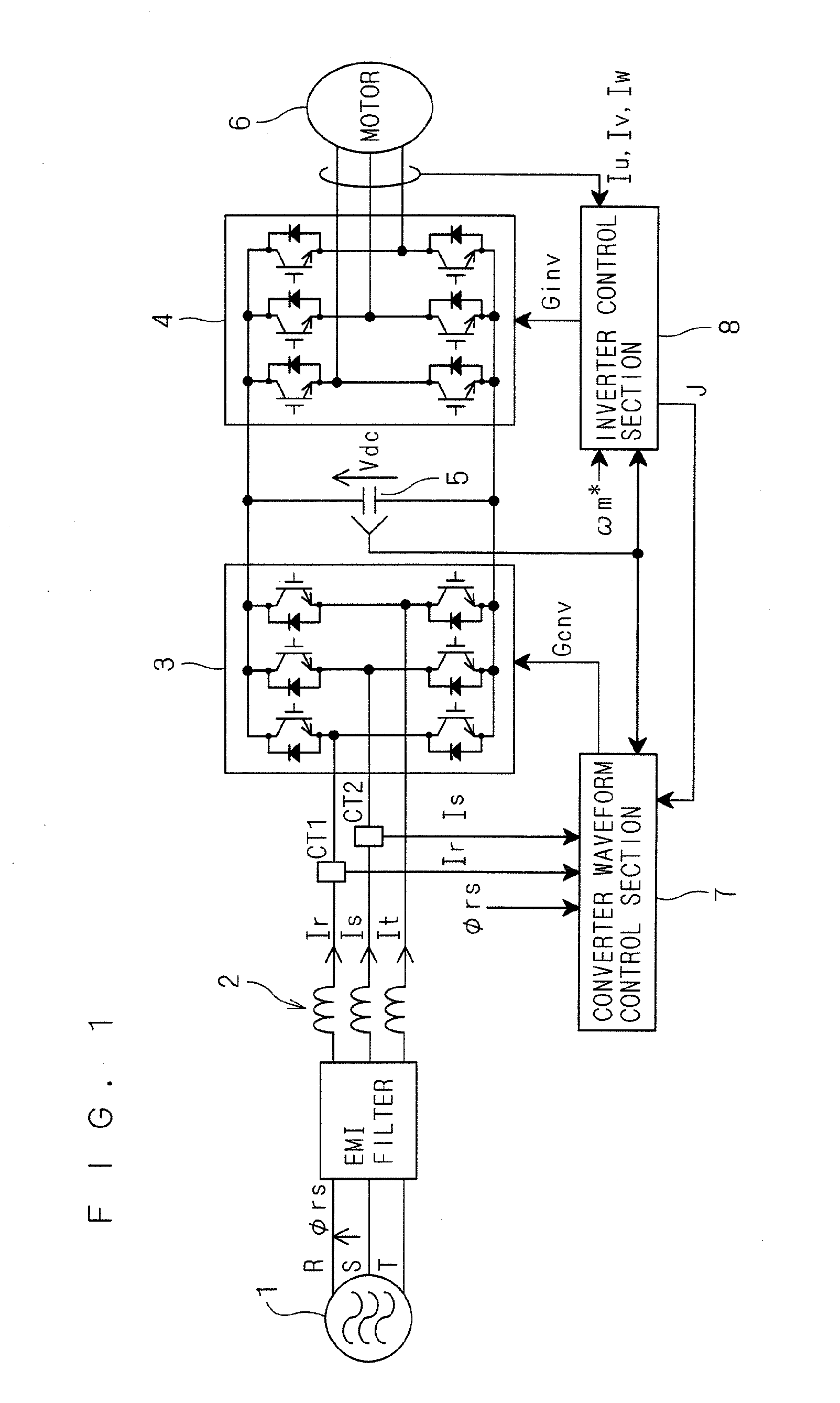
[0081]FIG. 4 is a circuit diagram showing a configuration of a converter waveform control section according to a first embodiment, which is employable as the converter waveform control section 7 of FIG. 1. In this configuration, a switching control signal G1 is outputted as the switching control signal Gcnv.

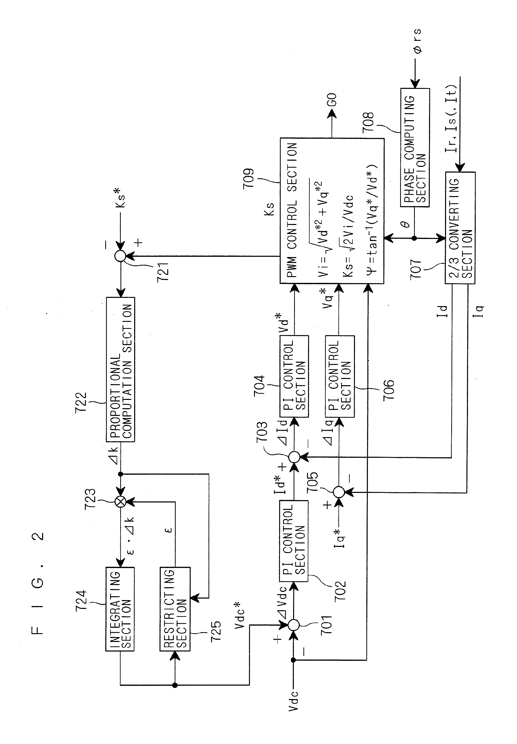
[0082]As adder-subtractors 701, 703, 705, PI control sections 702, 704, 706, a phase converting section 707, a phase computing section 708, and a PWM control section 709 employed in the converter waveform control section according to this embodiment, those shown in FIG. 2 are employed.

[0083]In this configuration, a voltage command value computing section 710 is employed instead of the adder-subtractor 721, the proportional computation section 722, the multiplying section 723, the integrating section 724, and the restricting section 725 which are shown in FIG. 2.

[0084]The voltage command value computing section 710 generates the DC voltage command val...

second embodiment

(b-3) Converter Control Method

[0092]FIG. 6 is a circuit diagram showing a configuration according to a second embodiment, which is employable as the converter waveform control section 7 of FIG. 1. In this configuration, a switching control signal G2 is outputted as the switching control signal Gcnv.

[0093]The configuration employed in the second embodiment has, in addition to the configuration employed in the first embodiment, voltage control sections 711, 713 and adders 712, 714.

[0094]The voltage control section 711 outputs, to the adder 712, a product ωLd·Id* of the d-axis current command value Id*, a d-axis inductance Ld of the reactor group 2, and an angular frequency ω of the power source voltage. The voltage control section 713 outputs, to the adder 714, a product ωLq·Iq* of the q-axis current command value Iq*, a q-axis inductance Lq of the reactor group 2, and the angular frequency ω. The d-axis inductance Ld and the q-axis inductance Lq are obtained by converting an inductan...

third embodiment

(b-4) Converter Control Method

[0097]FIG. 7 is a circuit diagram showing a configuration according to a third embodiment, which is employable as the converter waveform control section 7 of FIG. 1. In this configuration, a switching control signal G3 is outputted as the switching control signal Gcnv.

[0098]The configuration employed in the third embodiment is different from the configuration employed in the second embodiment, in that the voltage command value computing section 710 does not obtain the DC voltage command value Vdc* based on the d-axis voltage command value Vd*, but adopts an estimate value of the voltage Vi estimated to be √(Vd*2+Vq*2) in the PWM control section 709.

[0099]Needless to say, in this embodiment as well, the voltage control sections 711, 713 and the adders 712, 714 may be omitted similarly to the first embodiment.

[0100]Considering that there is the above-mentioned phase difference Ψ between the power source voltage Vs (an estimate value thereof) and the volta...


PUM


Abstract

A PI control section performs a PI control on a deviation which is a difference between a DC voltage command and a DC voltage, and outputs a d-axis current command value. A PI control section performs a PI control on a deviation which is a difference between the d-axis current command value and a d-axis current, and outputs a d-axis voltage command value. Based on the d-axis voltage command value and a q-axis voltage command value, a PWM control section outputs a switching control signal for controlling a switching operation of a converter. A voltage command computation section generates the DC voltage command based on the d-axis voltage command value.

Description

TECHNICAL FIELD[0001]The present invention relates to a converter control method, and particularly to a method for controlling a converter which rectifies a multi-phase current.BACKGROUND ART[0002]When a DC voltage is obtained by rectifying a current obtained from an AC power source, a higher power factor is desired. For example, in order to set a power factor at one in the use of a voltage-source PWM converter, it is necessary that an outputted DC voltage is set at a value higher than the peak value of an output voltage of the AC power source. If the specification of the output voltage of the AC power source in actual use is indefinite, the DC voltage is set to be a voltage relatively higher than the voltage according to the general specification.[0003]However, raising a set value of the DC voltage outputted from a converter means raising the maximum value of a voltage value given to an inverter device to which this DC voltage is inputted. This increases the loss of switching eleme...

Claims


Application Information

Patent Timeline
Patent Type & Authority Applications(United States)
IPC IPC(8): H02M7/217H02M7/12H02M7/48H02P6/06H02P6/08H02P6/182H02P6/28H02P21/22H02P27/08
CPCH02M1/4233H02M7/219Y02B70/126H02P21/0003H02M2007/53876Y02B70/10H02M7/53876H02P2201/03H02M7/53
Inventor KAWASHIMA, REIJI
Owner DAIKIN IND LTD
Why Eureka
Try Eureka