Ultrasonic diagnostic apparatus

Inactive Publication Date: 2011-02-17
HITACHI LTD
View PDF6 Cites 40 Cited by
  • Summary
  • Abstract
  • Description
  • Claims
  • Application Information

AI Technical Summary

Benefits of technology

[0027]According to the invention, it is possible to simplify the operation relating to the detection of

Problems solved by technology

On the other hand, in the bloodstream test such as the Doppler measurement or the CFM, since it is not possible to obtain correct information on the bloodstream because the cross-section of the blood vessel is deformed when the probe is placed on and pressed against the body tissue with an excessively strong force, it is preferable to perform the test with the pressurizing state which is gentler than that at the time of the B mode diagnosis.
In the case of such a testing process,

Method used


Image

  • Ultrasonic diagnostic apparatus
  • Ultrasonic diagnostic apparatus
  • Ultrasonic diagnostic apparatus

Examples


example 1

of Coupler Pressurization Evaluation

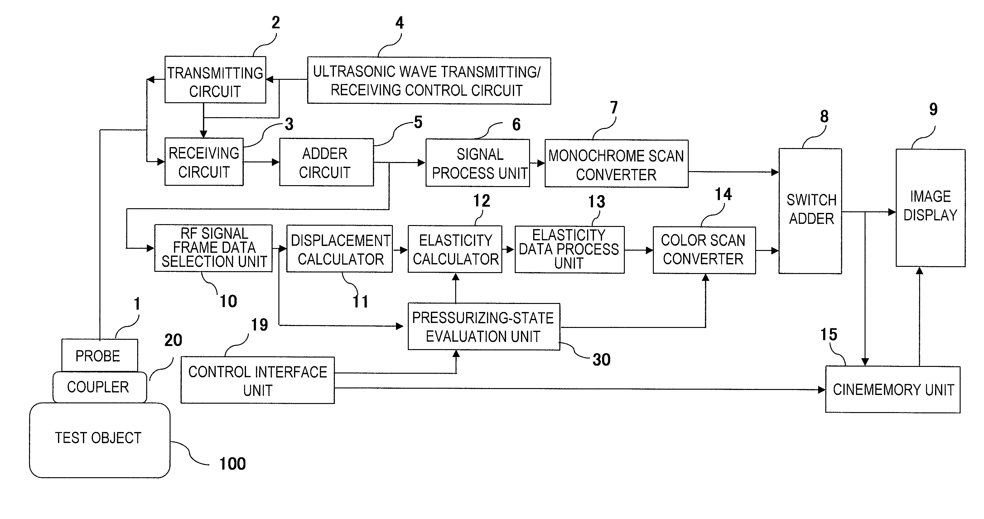
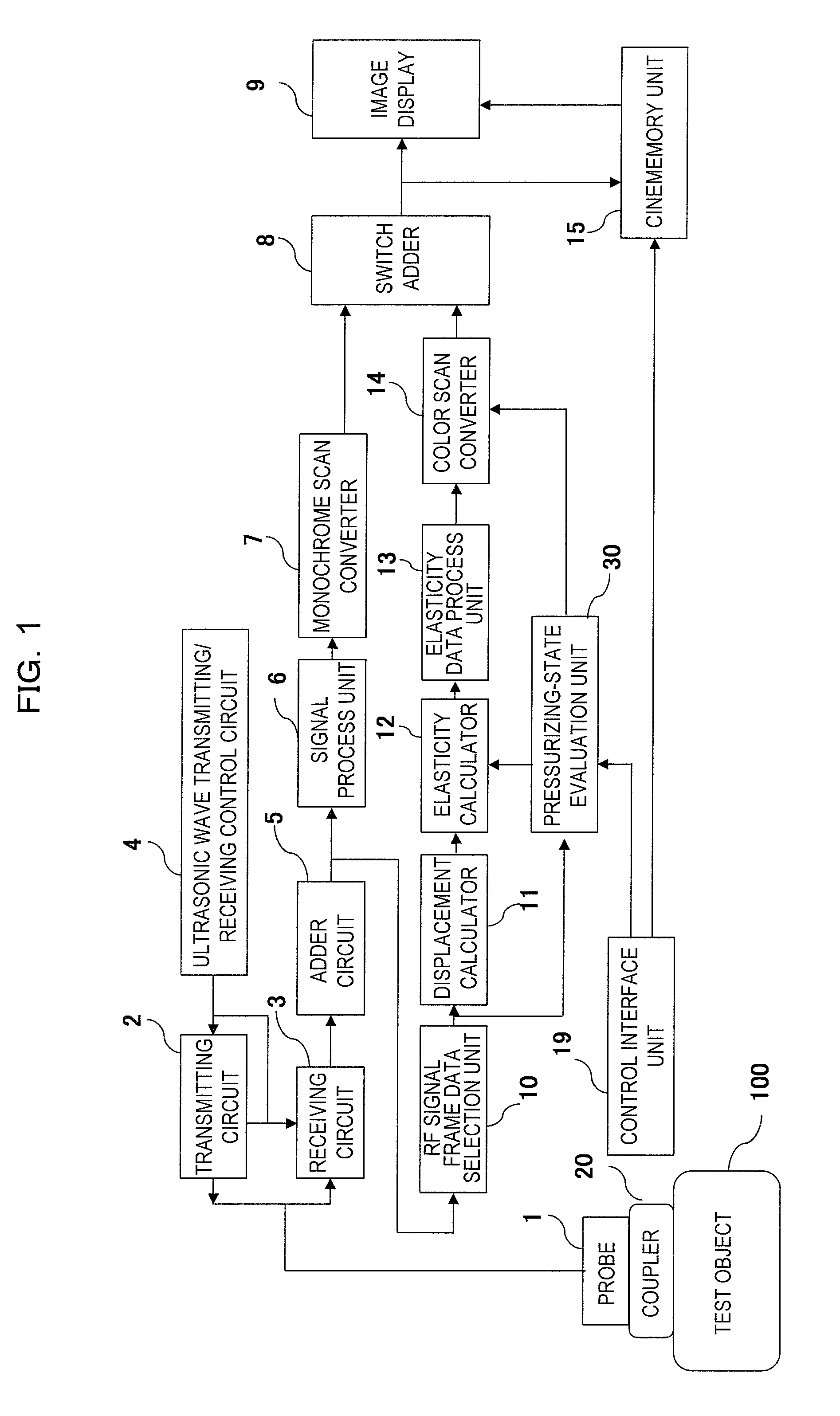
[0144]The coupler pressurization evaluation unit 54 detects the boundary between the elastic coupler 20 and the test object 100 based on the RF signal at an arbitrary timing t in the pressurized state of the elastic coupler 20 and obtains the thickness distribution Di(t) in the scanning direction in the pressurized state of the elastic coupler 20 similarly to the coupler pressurization evaluation unit 36 in Example 1. That is, the thickness distribution Di(t) in the scanning direction is obtained based on the speed of sound C and the time ti(t) from the point in time when the operator places the probe 1 on the test object 100 via the elastic coupler 20, applies a pressure, and transmits the ultrasonic waves in the pressurized state to the point in time when the intensity of the RF signal Qi(t) changes significantly.

[0145]Then, the thickness change distribution ΔDi(t) is obtained by the above formula (1) and the total distortion amount distribution...

example 2

of Coupler Pressurization Evaluation

[0146]The coupler pressurization evaluation unit 54 can obtain the total distortion amount Sij(t) by obtaining the displacement of the measurement point within the elastic coupler at the respective measurement points in time based on the RF signal frame data Qij(0) of the coupler echo region in the initial state, which is output from the RF signal frame data selection unit 10, and the RF signal frame data Qij(t) which is output from the RF signal frame data selection unit 10 at an arbitrary timing t in the pressurized state. Here, i is a coordinate in the scanning direction of the elastic coupler 20, and j is a coordinate of the thickness direction (depth direction) of the elastic coupler 20 as described above.

[0147]That is, the RF signal frame data receives the RF signal Qij(t) of the coupler echo region, which changes in real time in the pressurized state, obtains the displacement of the respective measurement points i and j by a know displaceme...

example 3

of Coupler Pressurization Evaluation

[0151]In Example 3 of the coupler pressurization evaluation, a pair of RF signal frame data obtained at different timings is obtained from the RF signal frame data selection unit 10 continuously at the respective measurement points in time from the initial state to the pressurized state as shown in FIG. 15. Then, the distortion changes ΔSij(t-k), . . . , ΔSij(t) at the respective measurement points i and j are obtained for the entire region in the depth direction of the elastic coupler 20 every time the pair of RF signal frame data is obtained. Subsequently, the distortion change ΔSi, j(t) of timing (t-1) and timing (t), which are temporally adjacent to each other, is obtained as shown in FIG. 15. Furthermore, in regard to a pair of temporally sequential RF signal frame data, the distortion changes ΔSi, j(t-k), . . . , ΔSij(t) are sequentially summed up to obtain the distortion change summed-up value ΣΔSij(t) at the present point in time. Subseque...


PUM


Abstract

The invention was made to simplify the operation relating to the detection of an absolute pressure applied to a test body by an ultrasonic probe and thereby to enhance usability. The fact that an elastic coupler has been attached to the ultrasonic wave transmitter/receiver surface and the fact that the elastic coupler is in an initial state with no pressure are detected (S2, S3), an initial thickness of the elastic coupler in the initial state is obtained (S6), the fact that the elastic coupler is in the pressurized state is detected based on the disappearance of a multiple echo which is included in an RF signal and caused due to the elastic coupler, the thickness of the elastic coupler in the pressurized state is obtained by detecting the boundary between the test body and the elastic coupler in the pressurized state, the thickness change is obtained based on the thickness in the pressurized state and the initial thickness (S7), and the absolute pressure applied to the test object is evaluated based on the thickness change and the pre-set elasticity property of the elastic coupler (S8).

Description

TECHNICAL FIELD [0001]The present invention relates to an ultrasonic diagnostic apparatus, and particularly to an ultrasonic diagnostic apparatus with a function for evaluating a pressure to be applied to a test object by an ultrasonic probe at the time of a test such as a diagnosis by a tomographic image (B mode image) or elasticity information of a body tissue of a test object, or a bloodstream diagnosis by Doppler measurement or a color flow mode (CFM).BACKGROUND ART [0002]Generally, an ultrasonic diagnostic apparatus is for performing a diagnosis such that ultrasonic waves are transmitted into a body of a test object from an ultrasonic probe (hereinafter, simply referred to as a probe), a reflected echo signal of the ultrasonic waves which have been reflected from the inside of the body is received by the probe, and an image or the like which is suitable for the test of a tissue, a function, or the like inside the body is created based on the received reflected echo signal (RF s...

Claims


Application Information

Patent Timeline
IPC IPC(8): A61B8/14
CPCA61B5/6843A61B8/06A61B8/488A61B8/4281A61B8/485A61B8/13Y02A90/10
Inventor MATSUMURA, TAKESHI
Owner HITACHI LTD
Why Eureka
Try Eureka