
Marine energy extraction systems and units

a technology for energy extraction systems and submarines, applied in the direction of electric generator control, machines/engines, mechanical equipment, etc., can solve the problems of inability to sustain indefinitely reliance on fossil fuels as primary energy sources, and no prior conceived system or method has achieved the efficiency or cost-effectiveness required to make wave-powered energy a viable alternative energy sour

Inactive Publication Date: 2011-02-24
BENSON ROBERT A
View PDF5 Cites 9 Cited by
  • Summary
  • Abstract
  • Description
  • Claims
  • Application Information

AI Technical Summary

Benefits of technology

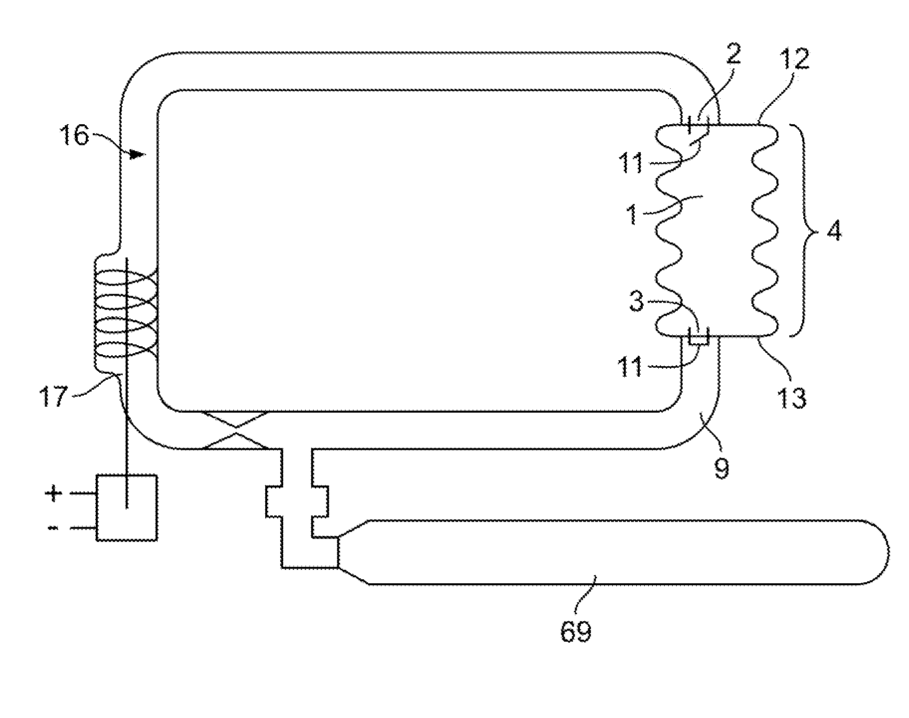
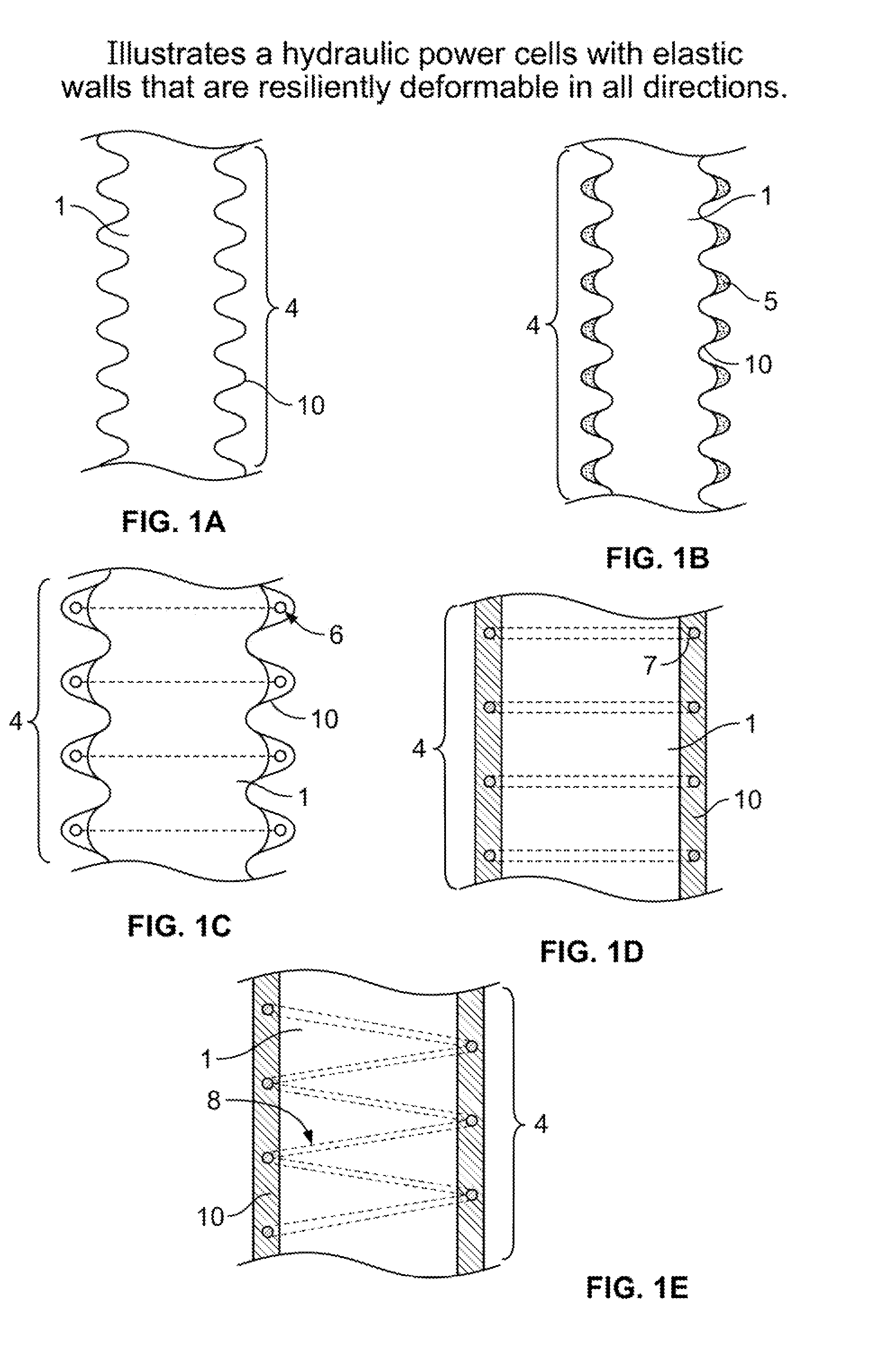
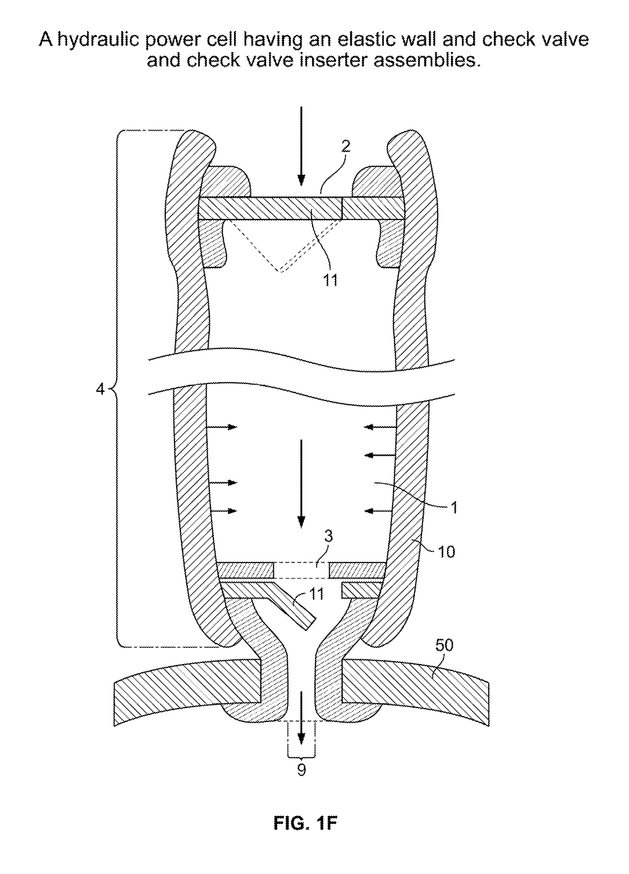
[0011]a tubular member having strengthened elastic walls which are resiliently deformable in all directions,
[0023]a tubular member having strengthened elastic walls which are resiliently deformable in all directions,

Problems solved by technology

With a finite supply of fossil fuels available and growing concerns over the impact of carbon dioxide, continued reliance on fossil fuels as a primary source of energy is not indefinitely sustainable.
Numerous systems have been developed in an attempt to efficiently capture the energy of waves; however, no prior conceived systems or methods have achieved the efficiency or cost-effectiveness required to make wave-powered energy a viable alternative energy source.
Such environments are prone to violent storms and the deleterious impact of salt water, plant life, and animal life.

Method used


Image

  • Marine energy extraction systems and units
  • Marine energy extraction systems and units
  • Marine energy extraction systems and units

Examples


example 1

Calculation of Possible Energy Generation from Marine Energy Extraction

[0083]A simple calculation assumes an average changing head of one foot per second with the entire hydraulic mass (water moved through all hydraulic cell structures in a mat) weighing 10,000 tons. Extrapolating such an assumption yields 20,000,000 ft. lbs. / sec. or 34,000 HP or 27,000 kw / sec.

example 2

Typical Specifications for Elastic and Flotation Material Used in Marine Energy Extraction (MEX) Components

[0084]

 1)Basic sheet or tubular stocksheet thickness ⅛″-4.0″tube diameter 0.005″-12″ 2)Durometer60A ± 5 Rockwell 3)Basic ingredients:Hycar ~45%PVC ~45%Plasticizers ~10% 4)Preferably no fabric or filler 5)Tensile (ASTM D-412-68)~2,500 p.s.i. 6)Ultimate elongation~380% 7)Ross flexing test per ASTM D 1052-551″× 6″×¼″ thick sample cycled 100 times / min.through 90° - no failure at 1,000,000 cycles 8)Tear strength - Graves Tear ASTM D 1004Longitudinal 190# / 11Transverse 190# / 11 9)Puncture resistance MIL-P-6396CThree tests: 135, 129, & 122#10)Abrasion resistance ASTM D 1630-61263, 244, 240 (3 results, values are relativeratios to natural rubber.11)Accelerated weathering - carbon arc without waterASTM 0750-68 & G23-69Tensile Tests (ASTM D-4 12-68)TimeUltimateUltimate(hrs.)TensionElongation 02,241 p.s.i.384%222,224 p.s.i.368%442,045 p.s.i.345%662,004 p.s.i.318%881,845 p.s.i.269%12)Low tem...

example 3

Tube Formation for Use as Tubular Member for Hydraulic Power Cell

[0085]A basic hydraulic power cell is preferably composed of an inexpensively extruded tube of the typical elastic material, Example 2, within which, after cutting or otherwise producing a correct tube length, standard valving, check valve-like structures, usually of the same elastic material and optionally, connector provisions, are inserted, bonded or otherwise positioned such that a simple, elastically deformable, one-way liquid flow hydraulic power cell is configured. The HPC structure can be then utilized in an appropriate mat or other marine energy extraction system.


PUM


Abstract

A floating at sea or beached structure having hydraulic power cells capable of capturing, dissipating and distributing wave action energy comprising flexible mats with energy capture cells all preferably constructed of elastic structural and, where necessary, flotation materials with distributed energy being in the form of a pressurized hydraulic stream.

Description

CROSS-REFERENCE TO RELATED APPLICATIONS[0001]The present application claims priority to, and the benefit of, co-pending U.S. Provisional Application 61 / 274,806 filed Aug. 21, 2009. The contents of this provisional application is incorporated herein by reference in its entirety.FIELD OF THE INVENTION[0002]The present invention relates generally to systems for recovering energy from waves and, more particularly, the present invention relates to an apparatus and methods for transforming fluid displacement caused by waves into electrical power.BACKGROUND OF THE INVENTION[0003]Currently, the majority of global energy consumption comes from non-renewable sources, such as oil, coal, natural gas, and other such fossil fuels. The use of such fossil fuels in the global energy consumption releases substantial amounts of carbon dioxide and other pollutants into the atmosphere. With a finite supply of fossil fuels available and growing concerns over the impact of carbon dioxide, continued relian...

Claims


Application Information

Patent Timeline
Patent Type & Authority Applications(United States)
IPC IPC(8): F03B13/22
CPCF03B13/182F03B13/188F03B13/20F05B2250/61F05B2260/406Y02E10/30
Inventor BENSON, ROBERT A.
Owner BENSON ROBERT A
Learn More