Turbine generator system

a generator system and turbine technology, applied in the direction of machines/engines, mechanical energy handling, mechanical apparatus, etc., can solve the problems of reducing the lubricant concentration of the working medium in the condenser, degrading the lubricating state of the bearings, and not easily evaporated lubricant, so as to achieve sufficient lubrication and enhance the lubricating ability

Active Publication Date: 2011-03-03
KAWASAKI HEAVY IND LTD
View PDF7 Cites 17 Cited by
  • Summary
  • Abstract
  • Description
  • Claims
  • Application Information

AI Technical Summary

Benefits of technology

[0019]In accordance with the above described present invention, the working medium converted into a vapor phase in the evaporator having a high pressure is supplied to the turbine power generation unit, while the lubricant is not easily evaporated, and therefore the working medium in a liquid phase with a high lubricant concentration remains at the lower portion of the evaporator. Since the working medium in a liquid phase with a high lubricant concentration is supplied from the evaporator having a high pressure to the constituent to be lubricated in the turbine power generation unit through the feeding passage, the constituent to be lubricated can be sufficiently lubricated. Therefore, it is not necessary to mix a large quantity of lubricant into the working medium for the purpose of enhancing its lubricating ability, and as a result, heat transmissibility of the evaporator and the condenser is not impeded.

Problems solved by technology

However, in a method in which the working medium is supplied from the condenser to the bearings like the technique disclosed in patent literature 1, the lubricant remains in the evaporator, because the working medium is easily evaporated in the evaporator but the lubricant is not easily evaporated therein.
This results in a lowered lubricant concentration of the working medium in the condenser.
In addition, because of a low pressure of the working medium, the lubricated state of the bearings becomes degraded.
If a large quantity of lubricant is mixed into the working medium to improve the lubricated state of the bearings in the turbine generator, heat transmissibility of the evaporator and the condenser is impeded, which is undesirable.

Method used


Image

  • Turbine generator system
  • Turbine generator system
  • Turbine generator system

Examples


first embodiment

The First Embodiment

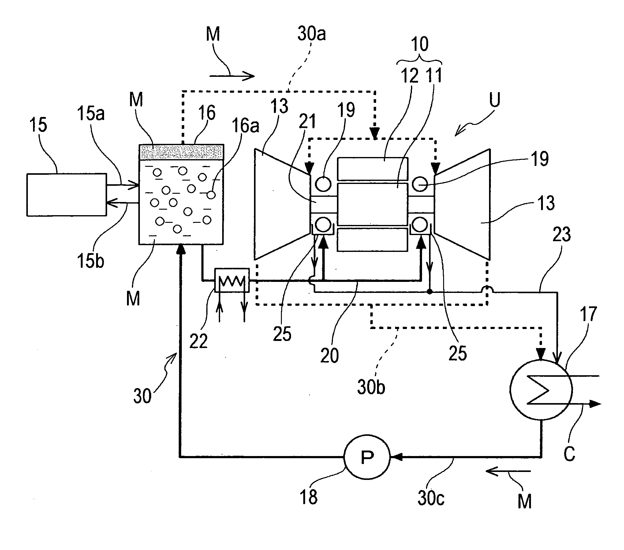
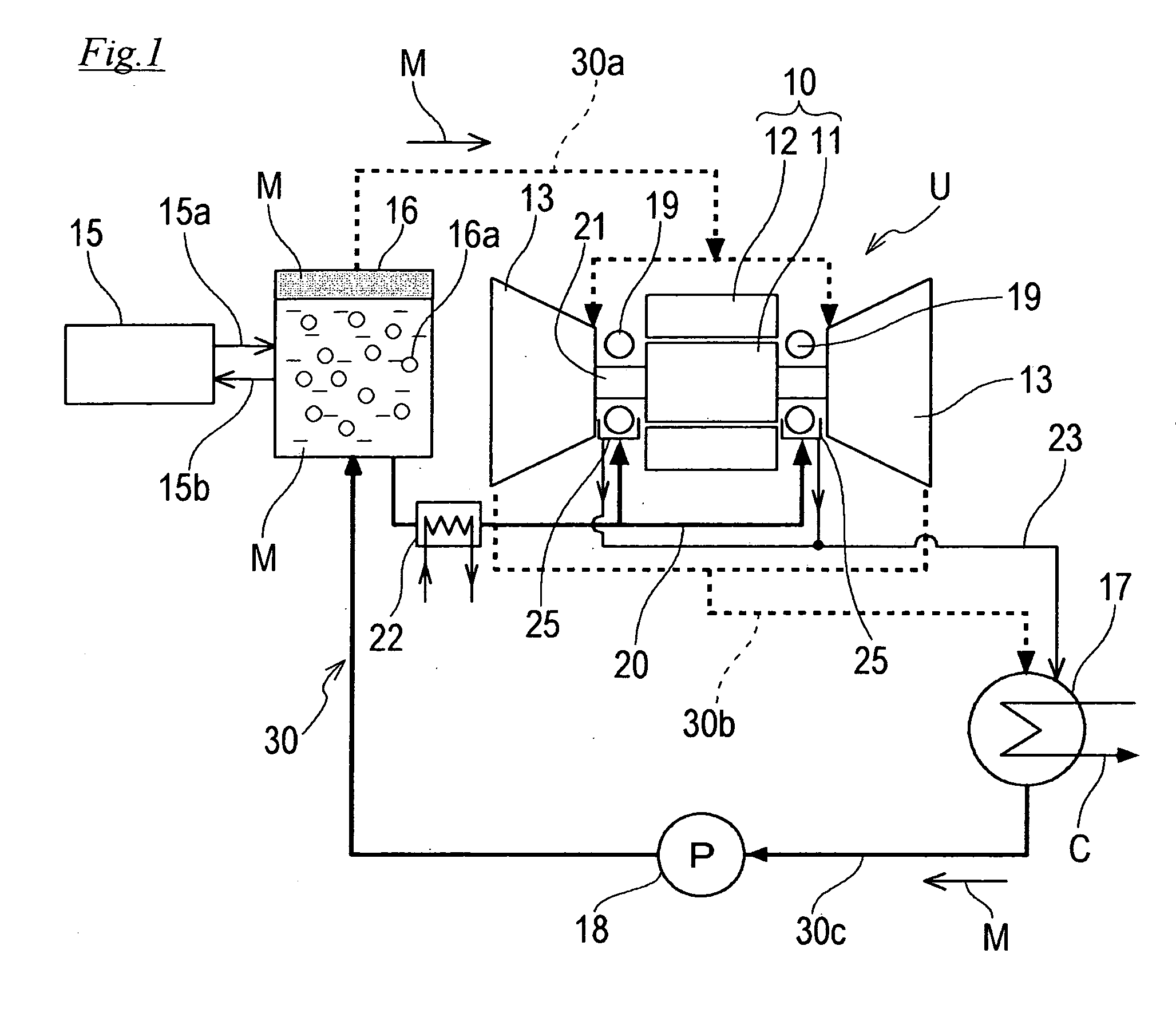
[0026]Referring to FIG. 1, a turbine generator system according to Embodiment 1 of the present invention comprises a turbine power generation unit U including a generator 10 and turbines 13 for driving the generator 10. On a medium passage 30 through which a working medium M for the turbines 13 is circulated, an evaporator 16 of a full liquid type, a condenser 17 and a medium feeding pump 18 are provided. The evaporator 16 is configured to receive heat from a heat source 15 by heat exchange to evaporate the working medium M and supplies the working medium M in a vapor phase to the turbine power generation unit U via a vapor phase medium feeding passage 30a. After rotating the turbines 13 in the turbine power generation unit U, the working medium M is fed to the condenser 17 via a vapor phase medium recovery passage 30b. The working medium M is liquefied in the condenser 17, and supplied to the evaporator 16 after its pressure is raised by the medium feeding pump ...

second embodiment

The Second Embodiment

[0043]FIG. 3 shows a turbine generator system according to Embodiment 2 of the present invention. In Embodiment 2, the same constituents as those of Embodiment 1 shown in FIG. 1 are designated by the same reference characters and will not be described repetitively in detail. Although in Embodiment 1, the evaporator 16 of a full liquid type is used as shown in FIG. 1, an evaporator 16 of a falling liquid film type is used in Embodiment 2 as shown in FIG. 3. The evaporator 16 of a falling liquid film type is configured in such a manner that a circulating pump 27 provided on a circulating passage 29 disposed for allowing communication between the lower portion and the upper portion of the evaporator 16 causes the working medium M in a liquid phase to be taken out from the lower portion of the evaporator 16 and to be showered to the heat transmission pipes 16a inside the evaporator 16 through an injection port of an injection pipe 26 disposed at the upper portion in...

third embodiment

The Third Embodiment

[0048]FIG. 4 shows a turbine generator system according to Embodiment 3 of the present invention. Embodiment 3 uses the evaporator 16 of a falling liquid film type, similarly to Embodiment 2. In FIG. 4, the same constituents as those of Embodiment 2 shown in FIG. 3 are designated by the same reference characters and will not be described repetitively in detail, but only different constituents will be described.

[0049]In Embodiment 2 shown in FIG. 3, the working medium M in a liquid phase is supplied to the bearings 19 through the feeding passage 20A which branches at the outlet of the circulating pump 27 provided on the circulating passage 29 for allowing communication between the upper portion and the lower portion of the evaporator 16. On the other hand, in Embodiment 3 shown in FIG. 4, each bearings 19 is provided with an injection unit 33 for injecting the working medium M in a liquid phase to the bearing 19, the lower portion of the evaporator 16 is coupled t...


PUM


Abstract

Provided is a turbine generator system capable of sufficiently lubricating a bearing without impeding heat transmissibility of an evaporator and a condenser. The turbine generator system comprises a turbine power generation unit including a generator and a turbine for driving the generator, an evaporator which receives heat from a heat source and supplies the working medium in a vapor phase containing a lubricant to the turbine power generation unit, a condenser which condenses the working medium which has flowed through the turbine a medium feeding pump which raises a pressure of the condensed working medium and feeds the working medium to the evaporator, and a feeding passage through which the working medium extracted from the evaporator is supplied to bearings in the turbine power generation unit.

Description

BACKGROUND OF THE INVENTION[0001]1. Technical Field[0002]The present invention relates to a turbine generator system capable of sufficiently lubricating bearings in a binary turbine utilizing waste heat.[0003]2. Background Art[0004]In recent years, a binary turbine generator system which uses as a heat source waste heat such as discharged hot water which has a temperature lower than 100 degrees C. and is generated in a large quantity in manufacturing processes in iron mills, ceramic engineering, etc, has attracted an attention, as a system intended to achieve energy saving and reduction of warming gases by using as a working medium, a medium with a low boiling point, other than water. In such a binary turbine generator system, in a case where the working medium itself has a lubricating ability, the working medium is supplied from a condenser to constituents to be lubricated, such as bearings in a turbine generator, to lubricate the bearings (see patent literature 1).[0005]Patent Lit...

Claims


Application Information

Patent Timeline
Patent Type & Authority Applications(United States)
IPC IPC(8): F01D25/22H02K7/08F01D25/12
CPCF01D25/20F01D25/22F05D2220/31F05D2240/54F05D2210/13F01K25/06
Inventor YAMASHITA, SEIJIKARIYA, DAISUKESHIMIZU, HAJIMEMIYAKE, NAOKIOKUMURA, TAKESHI
Owner KAWASAKI HEAVY IND LTD
Why Eureka
Try Eureka