Loop geothermal system

a geothermal system and loop technology, applied in mechanical equipment, machines/engines, light and heating equipment, etc., can solve the problems of increasing liability, complicating permitting, increasing the risk of earthquakes, and affecting the surface of the earth

Inactive Publication Date: 2011-03-03
MCHARGUE TIMOTHY REED
View PDF27 Cites 43 Cited by
  • Summary
  • Abstract
  • Description
  • Claims
  • Application Information

AI Technical Summary

Benefits of technology

[0022]In this embodiment, intersecting boreholes are lined with a continuous pipe that contains the production fluid throughout its circulation in the earth's subsurface and prevents the production fluid from directly contacting or chemically interacting with the subterranean hot rock formations. This continuous subterranean pipeline system provides a continuous pathway for fluid flow and allows heat to transfer from the subterranean hot rock to the pipe and then to the production fluid as it contacts the hot pipe. Delivery of the hot production fluid to a power plant located on the earth's surface provides the opportunity to generate electricity.
[0023]A novel aspect of this embodiment is the opportunity it affords to use a wide variety of potential fluids as the production fluid as well as the ability to rapidly and easily change production fluids as subterranean temperatures change or as conditions in the power plant change. The user has the option to use fluids or gasses other than water as production fluids in order to optimize the thermal properties of the production fluid to the local thermal conditions of the earth's subsurface, and the thermal requirements of the power plant. For example, one may choose to utilize supercritical fluids (U.S. Pat. No. 6,668,554 by D. W. Brown, 2003) or any hydrocarbon or refrigerant as the production fluid to feed a power plant. The potential to use fluids or gasses other than water as the production fluid will save money by providing the potential to drill cooler subterranean rocks at shallower depths where porosity and permeability are higher, and by reducing the need to artificially fracture the subterranean rock formations.

Problems solved by technology

Problems with this approach to geothermal energy production from hot dry rock are numerous and include:1. Flow of water from injection well bores to producing well bores usually requires either the expansion of natural fractures or the creation of new fractures.
This is expensive, and not always successful because the fractures generated at the injection well bore(s) may not intersect fractures at the producing well bore(s).2. The generation of fractures in the earth's subsurface may be accompanied by earthquakes which may cause damage at the earth's surface and thereby increase liability and complicate permitting.
Further, the risk of earthquakes is increased by introducing water or other fluid, which may serve as a lubricant, into the fractures.3. Hot water that travels through subterranean rock at high temperature interacts chemically with the subterranean rock and dissolves some mineral components of the subterranean rock.
The deposited mineral components may coat and eventually clog pipes unless remedial actions are taken to prevent it.
The remedial actions add to the cost of the produced energy.4. Steam is derived from water produced from subterranean hot rock formations.
Subterranean rock of this high temperature typically is found at great depth and at high pressures where porosity and permeability are small.5. Fluids other than water can be injected into the subterranean hot rock formations but options are limited due to considerations of chemical interaction with the subterranean hot rock formations and potential pollution of aquifers.
Considerable expense is saved by locating the power plant on the earth's surface.
Furthermore, the interstitial fluids remain available to conduct heat to the well bores.3. Because circulating production fluid never comes in direct contact with subterranean rock formations, being separated from the subterranean hot rock formations by pipe, there is no opportunity for the production fluid to interact chemically with the subterranean hot rock.

Method used


Image

  • Loop geothermal system
  • Loop geothermal system

Examples


Embodiment Construction

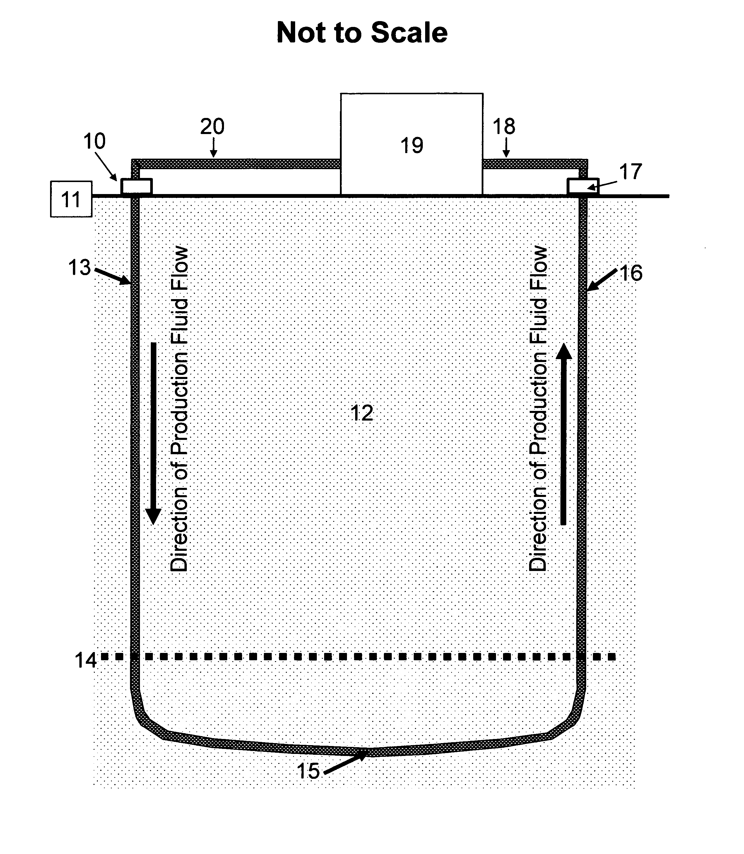
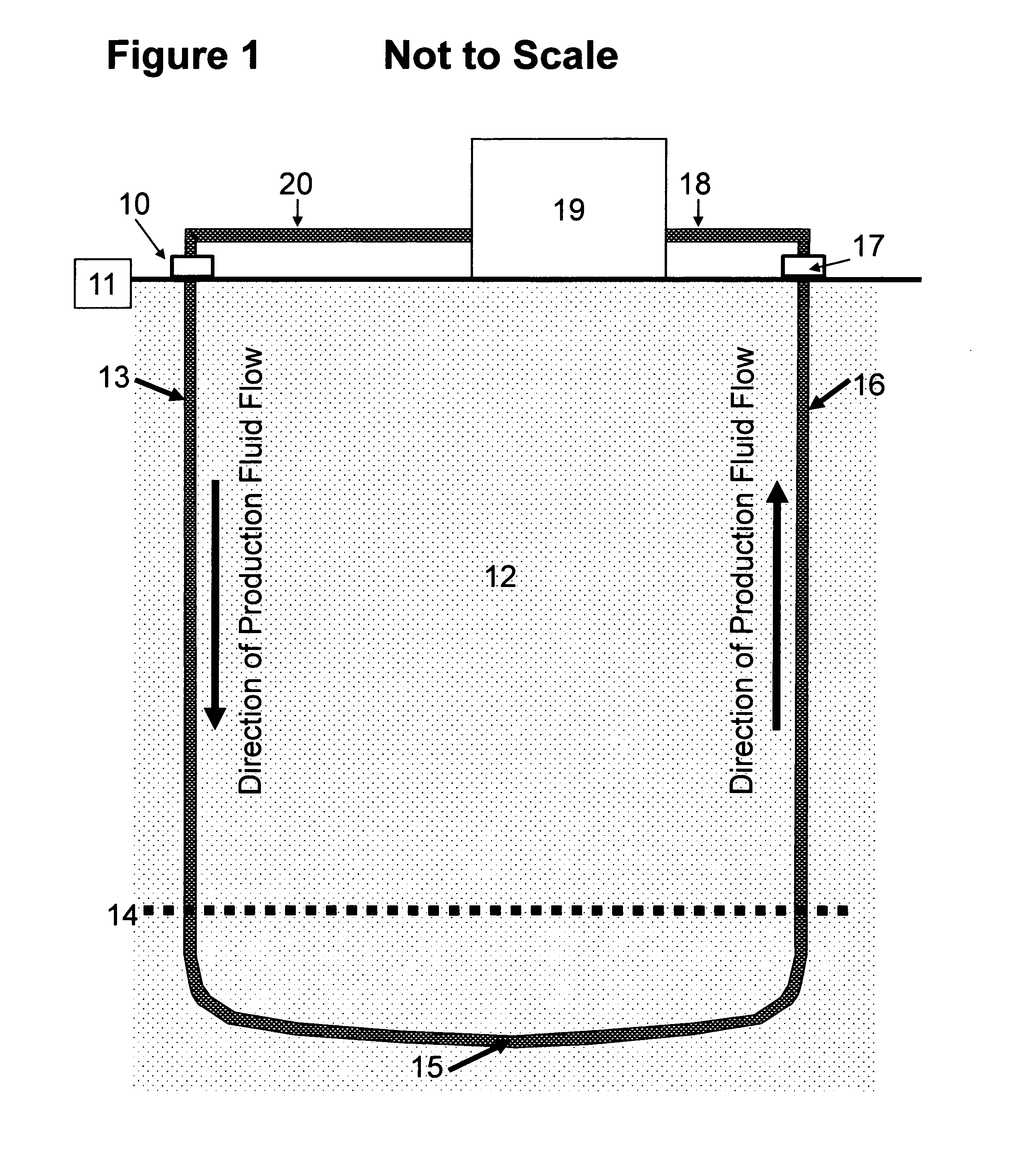
[0021]A novel approach to recovering hot fluid and / or gas for use in geothermal power generation is described here and called a Loop Geothermal System. The novel approach is to circulate fluid or gas, here referred to as production fluid, through subterranean hot rock formations via a continuous subterranean pipeline formed by cementing continuous pipe along the path made by the intersection of two or more separate bore holes. Drilling intersecting well bores and construction of a continuous subterranean pipeline through the intersected well bores is an accepted practice in the petroleum industry and can be contracted commercially, for example SperryConnect Well Intersection Service, a subsidiary of Halliburton. Application of this technology to the geothermal industry is novel and offers several distinct advantages over standard procedures that rely on water flow through subterranean fractures, for example U.S. Pat. No. 3,786,858 to R. M. Potter, E. S. Robinson, and M. C. Smith (19...


PUM


Abstract

One embodiment of a system of geothermal energy production containing a production fluid circulated entirely within a continuous subterranean pipeline (13 and 16) while below the earth's surface (11) so that the production fluid is heated, via the encasing pipe, by surrounding subterranean hot rock (12). By directing the heated production fluid through said continuous subterranean pipeline up to the earth's surface and through a power plant (19), energy can be produced from the hot production fluid.This system enables energy production from subterranean rock formations of moderate temperature at moderate depths because any production fluid, such as water, hydrocarbon, or refrigerant, can be used to optimize energy production. Furthermore, natural porosity and permeability of the subterranean rock formations at moderate depths may provide sufficient natural circulation of interstitial water to assist in heat transfer from large volumes of hot rock without the need of inducing artificial fractures.

Description

CROSS-REFERENCE TO RELATED APPLICATIONS[0001]This application claims the benefit of provisional patent application Ser. No. 61 / 275,142 filed 2009, Aug. 26, by the present inventor.FEDERALLY SPONSORED RESEARCH [0002]Not ApplicableSEQUENCE LISTING OR PROGRAM [0003]Not ApplicableBACKGROUND[0004]1. Field[0005]This application relates to geothermal energy generation, specifically to the heating of a fluid or gas during transport through subterranean hot rock formations while continuously enclosed within a pipeline formed by intersecting well bores, then delivered to a power plant at the earth's surface, and subsequently re-injected through the pipe back underground in a continuous closed loop.[0006]2. Prior Art[0007]Hot Dry Rock geothermal energy systems rely on the injection of water (U.S. Pat. No. 3,786,858, Potter, Robinson and Smith, 1974) or other fluid (U.S. Pat. No. 4,060,988, Arnold, 1977; U.S. Pat. No. 6,668,554, Brown, 2003) through well bores into subterranean hot rocks and re...

Claims


Application Information

Patent Timeline
Patent Type & Authority Applications(United States)
IPC IPC(8): F03G7/00F24J3/08
CPCF24J3/081Y02E10/12F24T10/10Y02E10/10
Inventor MCHARGUE, TIMOTHY REED
Owner MCHARGUE TIMOTHY REED
Why Eureka
Try Eureka