
Nozzle for feeding combustion media into a furnace

a technology of combustion media and nozzles, which is applied in the direction of combustion types, combustion using lump and pulverulent fuel, lighting and heating apparatus, etc., can solve the problems of oxidation, thinning of stainless steel plates, and eventual closure of air and fuel passages of nozzles, so as to prevent thermal distortion and prolong service life

Active Publication Date: 2011-03-03
R V INDS
View PDF4 Cites 11 Cited by
  • Summary
  • Abstract
  • Description
  • Claims
  • Application Information

AI Technical Summary

Benefits of technology

[0011]This invention provides an improved fuel nozzle or air nozzle that is better able than existing designs to prevent thermal distortion due to exposure to radiation and hot gases in a furnace. The invention can also be applied to existing designs to extend their service life.
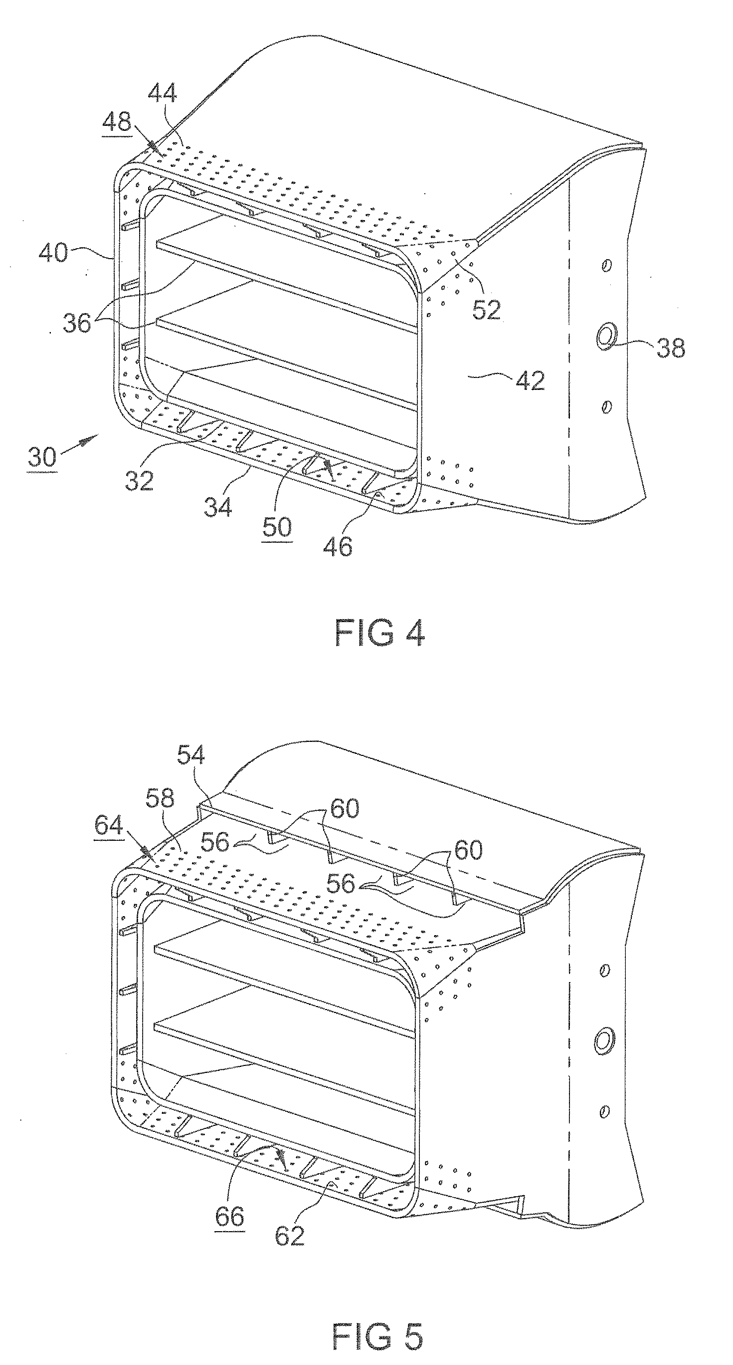
[0012]Briefly, closely-spaced cooling holes are provided in the walls of the nozzle tip wherever exposure to radiation is expected, preferably in offset or parallel patterns. Air, generally at a low pressure, e.g., less than about 30 in. wg., flows through the holes, reducing the thermal gradient across the wall of the nozzle tip by conduction. The air flow also keeps flames away from the surfaces of the nozzle tip and thereby aids in inhibiting radiation impingement.
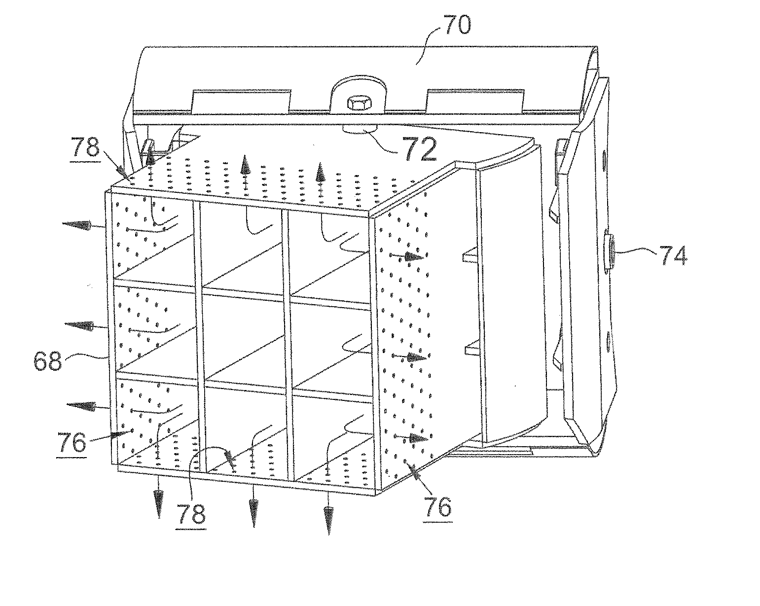
[0016]The array of openings becomes particularly advantageous when the nozzle tip is a tiltable and / or yawable nozzle tip, arranged so that the quantity of radiant heat, from combustion in the furnace, to which the foraminous wall of the nozzle tip is exposed varies as the nozzle tip is tilted. In the case of a tiltable nozzle tip, if the radiant heat to which the foraminous wall of the nozzle tip is exposed increases as the nozzle tip is tilted, the flow of air through the openings in the foraminous wall also increases, thereby more effectively moderating the temperature difference between the inner and outer surfaces of that wall.
[0017]In a version of the tiltable nozzle tip mounted for both pitch and yaw adjustment and having four walls, each of the walls can be provided with an array of openings providing for the flow of combustion-maintaining medium from its inner surface to its outer surface. In such an embodiment, regardless of the direction to which the nozzle tip is adjusted, an increased cooling effect is realized at the wall having the greatest exposure to radiant heat.

Problems solved by technology

The thermal gradients cause distortion of the nozzle tips, and can even cause eventual closure of their air and fuel passages.
Unprotected exposure to radiation also results in excessively high temperatures, oxidation, and thinning of the stainless steel plate.
Thermal distortion and high temperature oxidation of the nozzle tips cause heavy damage to the nozzle tips and deterioration of combustion performance, requiring frequent and expensive replacement.
Similar problems are encountered in the case of nozzle tips mounted for yaw adjustment or for both pitch and yaw adjustment.
Although the air-directing channels described in U.S. Pat. No. 6,260,491 are effective to reduce thermal distortion and high temperature oxidation of a nozzle tip, even a nozzle tip equipped with such air-directing channels is subject to eventual failure due to thermal distortion and oxidation when exposed to radiation and hot gases in a furnace over an extended time.
A problem inherent in conventional fuel and air nozzle tips, as well as in nozzle tips equipped with air-directing channels, is that the outside surfaces of the nozzle tips are exposed to high temperatures due to flame radiation, conduction of heat from hot gases, or a combination of radiation and conduction, while the fuel, air, or a combination of fuel and air passing through the inside of the nozzle is relatively cool, and tends to cool the inside surfaces of the nozzle.
The difference between the temperature of the outside surfaces and the temperature of the inside surfaces results in a high temperature gradient across the plates or castings that make up the nozzle.
When one side of a plate or casting is cooled while the other side becomes very hot due to furnace radiation, hot gas, or both, the plate or casting distorts, and the structural integrity of the nozzle is compromised.
The nozzle becomes less effective for its intended purpose, and its service life is shortened.

Method used


Image

  • Nozzle for feeding combustion media into a furnace
  • Nozzle for feeding combustion media into a furnace
  • Nozzle for feeding combustion media into a furnace

Examples


Embodiment Construction

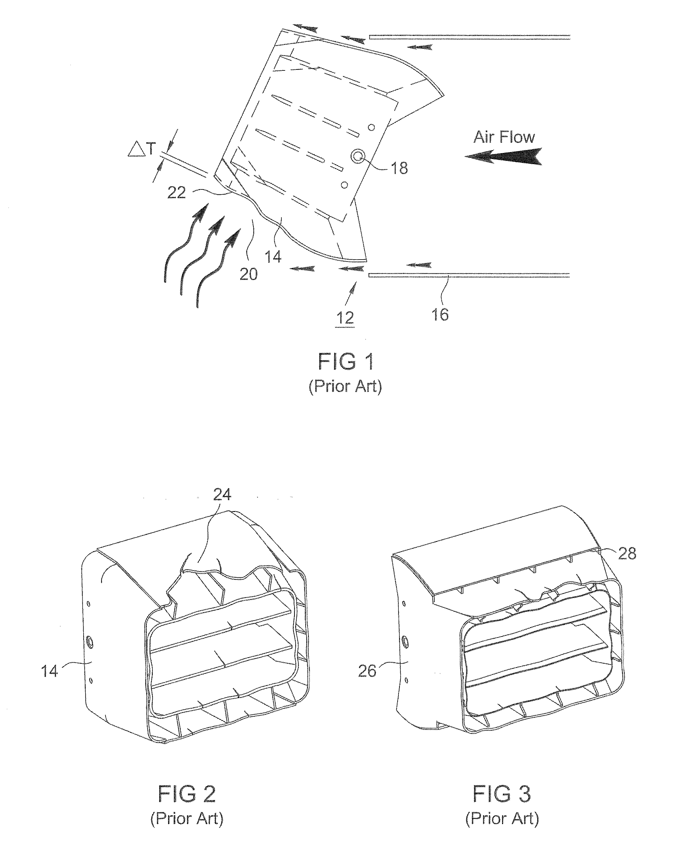
[0028]In the conventional nozzle of FIG. 1, coal along with air is delivered to the interior of a boiler furnace through a coal nozzle 12 and a tilting nozzle tip 14. Secondary air in conduit 16 is also delivered through the tilting nozzle.

[0029]The nozzle is mounted on trunnions, one of which is shown at 18, and tiltable on a horizontal axis. That is, its pitch can be adjusted. In FIG. 1, the nozzle tip is tilted upward. As shown by arrows, air flowing from conduit 16 through a leakage path between the conduit and the nozzle tip flows along the top wall of the nozzle tip, keeping the upper part of the nozzle tip cool. However, the air leaking through the space between the conduit and the lower part of the nozzle tip tends to separate from the nozzle tip allowing a dead zone 20 to exist adjacent the bottom wall 22 of the nozzle tip. As a consequence of the dead zone, the air flowing through the space between the conduit wall and the lower part of the nozzle tip has comparatively lit...


PUM


Abstract

In a boiler furnace having nozzles for introducing combustion media such as air and coal, nozzle tip walls that have the greatest exposure to radiant heat and hot gases are provided with arrays of air holes that allow air to flow to the exposed sides of the walls from the opposite sides in order to reduce the temperature difference between the two sides and thereby reduce thermal distortion and damage resulting from oxidation.

Description

FIELD OF THE INVENTION[0001]This invention relates to nozzles for feeding combustion media, for example pulverized coal and air, into a furnace. The invention has particular application in pulverized coal feeding nozzles and secondary air nozzles in the tangentially fired burners of steam generating boilers. The invention is also applicable to various other kinds of combustion media nozzles.BACKGROUND OF THE INVENTION[0002]Many coal-fired power plant boilers are designed for tangential firing, i.e., a configuration in which streams of pulverized coal and air are directed into a rectangular furnace compartment from columns of nozzles located in such a way as to generate a slowly rotating cyclonic fireball, which produces heat which in turn boils water in arrays of water tubes lining the walls of the compartment. Tangential firing is described in various patents including U.S. Pat. Nos. 4,252,069, 4,634,054, and 5,483,906.[0003]Tangentially fired boilers fueled by pulverized coal typi...

Claims


Application Information

Patent Timeline
IPC IPC(8): F23D1/02F23C5/06F23C7/00
CPCF23D1/00F23D2211/00F23D2214/00F23D2201/101
Inventor GRUSHA, JOHN
Owner R V INDS
Learn More