Cooling system and electronic apparatus applying the same therein

a technology of electronic equipment and cooling system, applied in the field of cooling system, can solve the problems of large thermal resistance, large thermal resistance in the whole cooling system, and easy large thermal resistance in the condensation area or portion

Active Publication Date: 2011-03-03
HITACHI LTD
View PDF11 Cites 68 Cited by
  • Summary
  • Abstract
  • Description
  • Claims
  • Application Information

AI Technical Summary

Benefits of technology

[0040]FIGS. 11A and 11B are cross-section views for showing the flat tube comparing to a circular tube of the conventional technology, for explaining behavior of refrigerant within the flat tub

Problems solved by technology

For that reason, heat resistance is generated at a connecting portion between the heat pipe and the heat radiating means, and the heat radiating means must be large in the size thereof, for the purpose of increasing the performances or capacity of heat radiation thereof, and therefore, in the similar manner to the cooling system of the water cooling mentioned above, there is a problem the cooling system as a whole comes to be large in the sizes or scales thereof.
For the purpose of transferring an amount of heats being large much more with the heat difference being smaller much more, it i

Method used


Image

  • Cooling system and electronic apparatus applying the same therein
  • Cooling system and electronic apparatus applying the same therein
  • Cooling system and electronic apparatus applying the same therein

Examples


Embodiment Construction

[0045]Hereinafter, embodiments according to the present invention will be fully explained by referring to the attached drawings.

[0046]First of all, detailed explanation will be given on a cooling system applying a thermo siphon therein, according to an embodiment of the present invention, by referring to FIGS. 1 to 12 attached herewith.

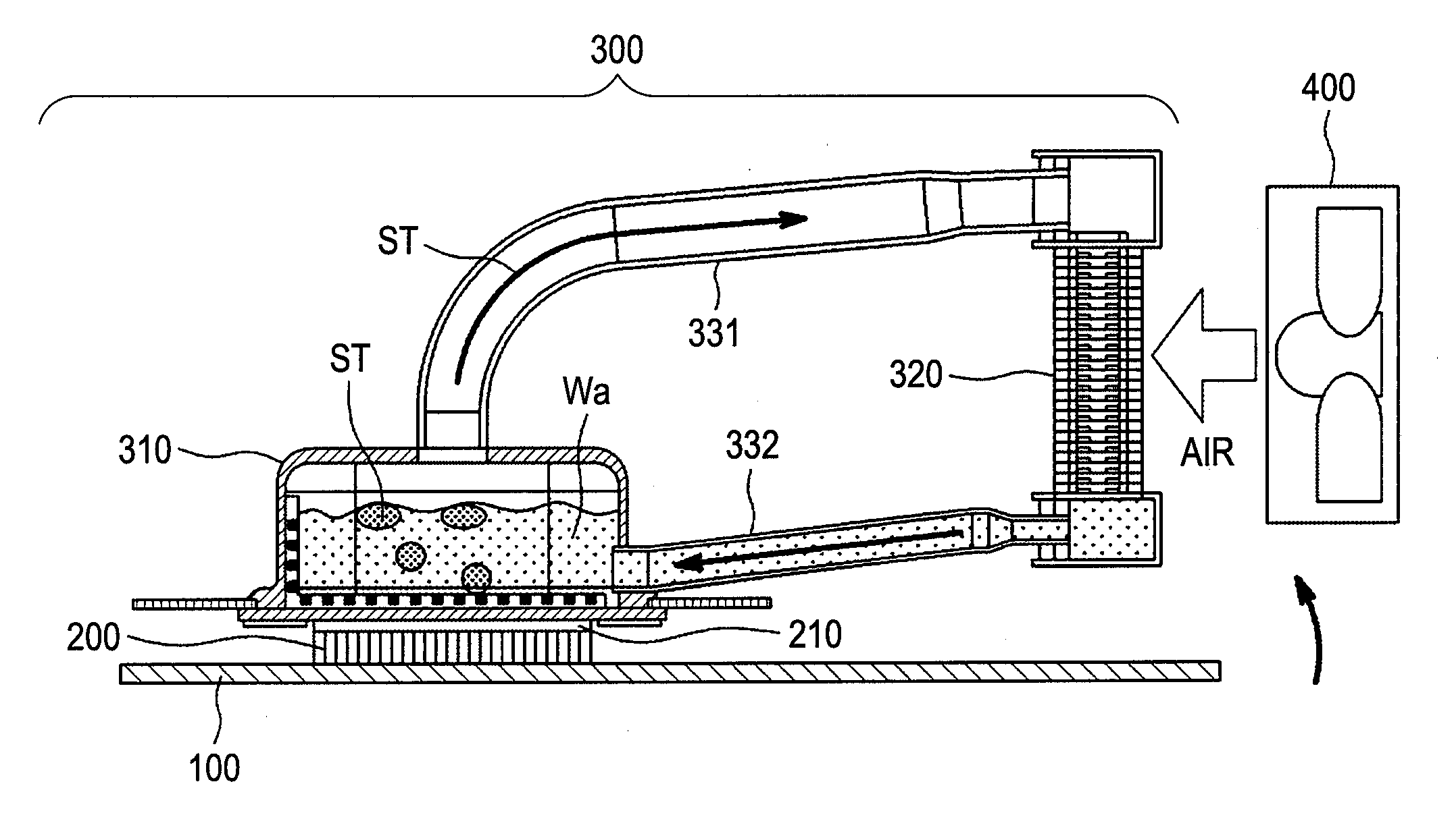
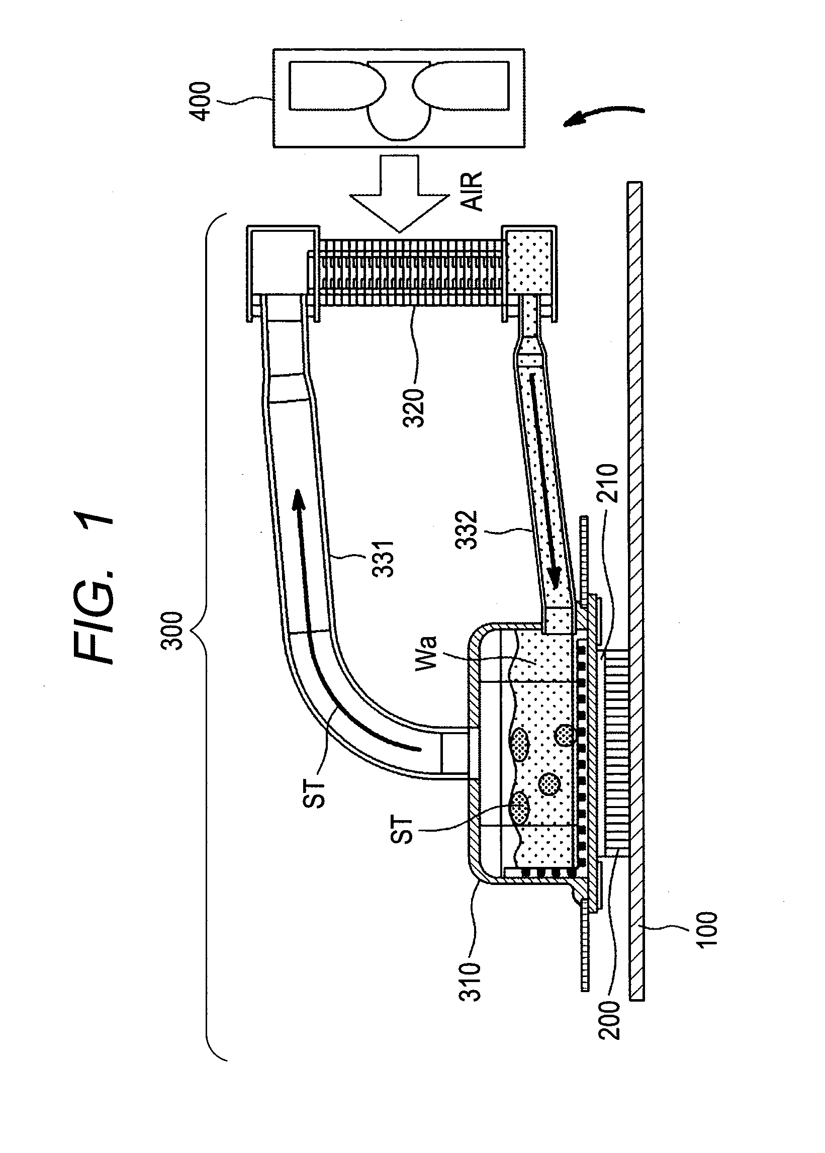
[0047]FIG. 1 shows the entire structures of the cooling system applying the thermo siphon therein, and in the figure, a reference numeral 100 depicts a printed circuit board, upon a surface of which are mounted a semiconductor device 200, as the heat generation source, such as, a CPU, etc., for example. And, on the surface of that semiconductor devices 200 is attached a heat-receiving jacket 310, which builds up a part of a cooling system applying the thermo siphon therein, according to the present invention. In more details, on the surface of the semiconductor device 200 is contacting a bottom face of the heat-receiving jacket 210, while pasting ther...


PUM


Abstract

A cooling system applying a thermo siphon therein, being superior in energy saving and/or ecology, with an effective cooling, and also an electronic apparatus applying that therein, in particular, for cooling a CPU 200 mounted on a printed circuit board 100 within a housing thereof, comprises a heat-receiving jacket 310, being thermally connected with a surface of the CPU generating heats therein, and for evaporating liquid refrigerant stored in a pressure-reduced inner space with heat generation thereof, a condenser 320 for receiving refrigerant vapor from the heat-receiving jacket within a pressure-reduced inner space thereof and for condensing the refrigerant vapor into a liquid by transferring the heats into an outside of the apparatus, a vapor tube 331, and a liquid return tube 332, with applying the thermo siphon for circulating the refrigerant due to phase change thereof, wherein the condenser forms fine grooves on an inner wall surface thereof along a direction of flow of the refrigerant, and is also formed flat in a cross-section thereof, for cooling the refrigerant vapor from the heat-receiving jacket on the inner wall surface thereof, efficiently.

Description

[0001]This application relates to and claims priority from Japanese Patent Application No. 2009-198179 filed on Aug. 28, 2009, the entire disclosure of which is incorporated herein by reference.BACKGROUND OF THE INVENTION[0002]The present invention relates to a cooling system for electronic apparatuses, such as, a server, mounting plural numbers of CPUs, each being a heat generation source, within an inside of a housing thereof, and it relates to a cooling system for enabling to achieve energy-saving and small-sizing of the cooling system, as well as, achieving a silent system with applying thermo-siphon therein, and further, an electronic apparatus being suitable to mount such the cooling system therein.[0003]In recent years, within an electronic apparatus, such as, the server, etc., representatively, for example, accompanying with an increase of processing speed thereof, plural numbers of so-called semiconductor devices, such as, central processing units (i.e., CPUs) are mounted o...

Claims


Application Information

Patent Timeline
IPC IPC(8): F28D15/02
CPCF28D1/05366F28D15/0266F28D15/046F28F1/325F28F13/187H01L2924/0002H01L23/427F28F2215/12H01L2924/00
Inventor TOYODA, HIROYUKINAKAJIMA, TADAKATSUKONDO, YOSHIHIROSASAKI, SHIGEYUKIIDEI, AKIOSATOH, SHIGEMASA
Owner HITACHI LTD
Why Eureka
Try Eureka