Moving body system and method of determining initial position of moving body

a moving body and initial position technology, applied in the direction of motor/generator/converter stopper, dynamo-electric converter control, instruments, etc., can solve the problems of disadvantageous cost of linear sensors and inability to determine the position of movable elements unambiguously

Active Publication Date: 2011-03-03
MURATA MASCH LTD
View PDF5 Cites 54 Cited by
  • Summary
  • Abstract
  • Description
  • Claims
  • Application Information

AI Technical Summary

Benefits of technology

[0006]Preferred embodiments of the present invention provide a system, technique and method of unambiguously determining an absolute position of a movable element using a position sensor having a measurement range that is shorter than a magnet array of the movable element so as to determine a position of the movable element more reliably.
[0011]Preferably, the length of the magnet array is longer than an arrangement pitch of the stationary elements so that, when a rear end of the magnet array faces a coil at a rear end of a stationary element on a back side, a front end of the magnet array can face a coil at a rear end of a stationary element on a front side. In this manner, it becomes possible to reduce the possibility that the magnet array only faces one stationary element, and increase the possibility that the magnet array faces a pair of left and right stationary elements. In the state where the magnet array faces a plurality of stationary elements, based on information that (i) the magnet array faces equally to both of left and right stationary elements, (ii) the magnet array faces one of the stationary elements in a wide range and faces the other of the stationary elements in a narrow range, etc., the position of the magnet array can be determined more reliably.
[0013]Preferably, the alternating current has a frequency that does not cause movement of the moving body following the alternating current, and the start-up unit measures direct current resistance of each of the coils of the stationary elements at the time of applying the direct current to the stationary elements when the power supply is turned on, determines alternating current impedance of each of the coils upon application of the alternating current, and determines inductance of each of the coils by removing the direct current resistance from the determined alternating current impedance. In this manner, inductance of each of the coils can be determined easily.

Problems solved by technology

Such a linear sensor is disadvantageous in terms of the cost.
In the case of using a position sensor having a measurement range that is shorter than the length of the movable element, at the time of the start-up operation, the position of the movable element cannot be determined unambiguously.

Method used


Image

  • Moving body system and method of determining initial position of moving body
  • Moving body system and method of determining initial position of moving body
  • Moving body system and method of determining initial position of moving body

Examples


Embodiment Construction

[0026]Hereinafter, preferred embodiments of the present invention will be described. The scope of the present invention shall be determined according to understanding of a person skilled in the art based on the description of the claims in consideration of the description of the specification and techniques known in this technical field.

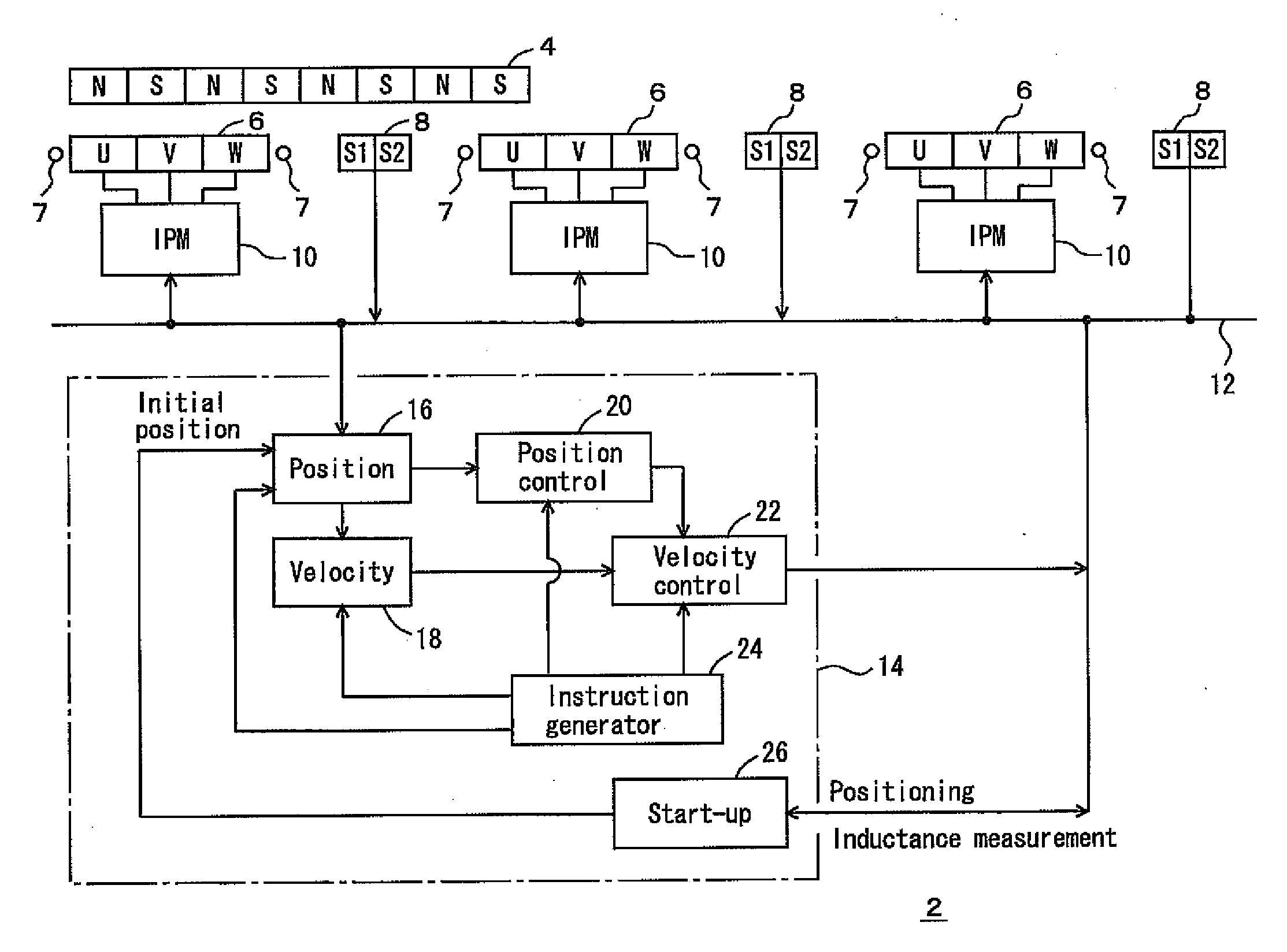
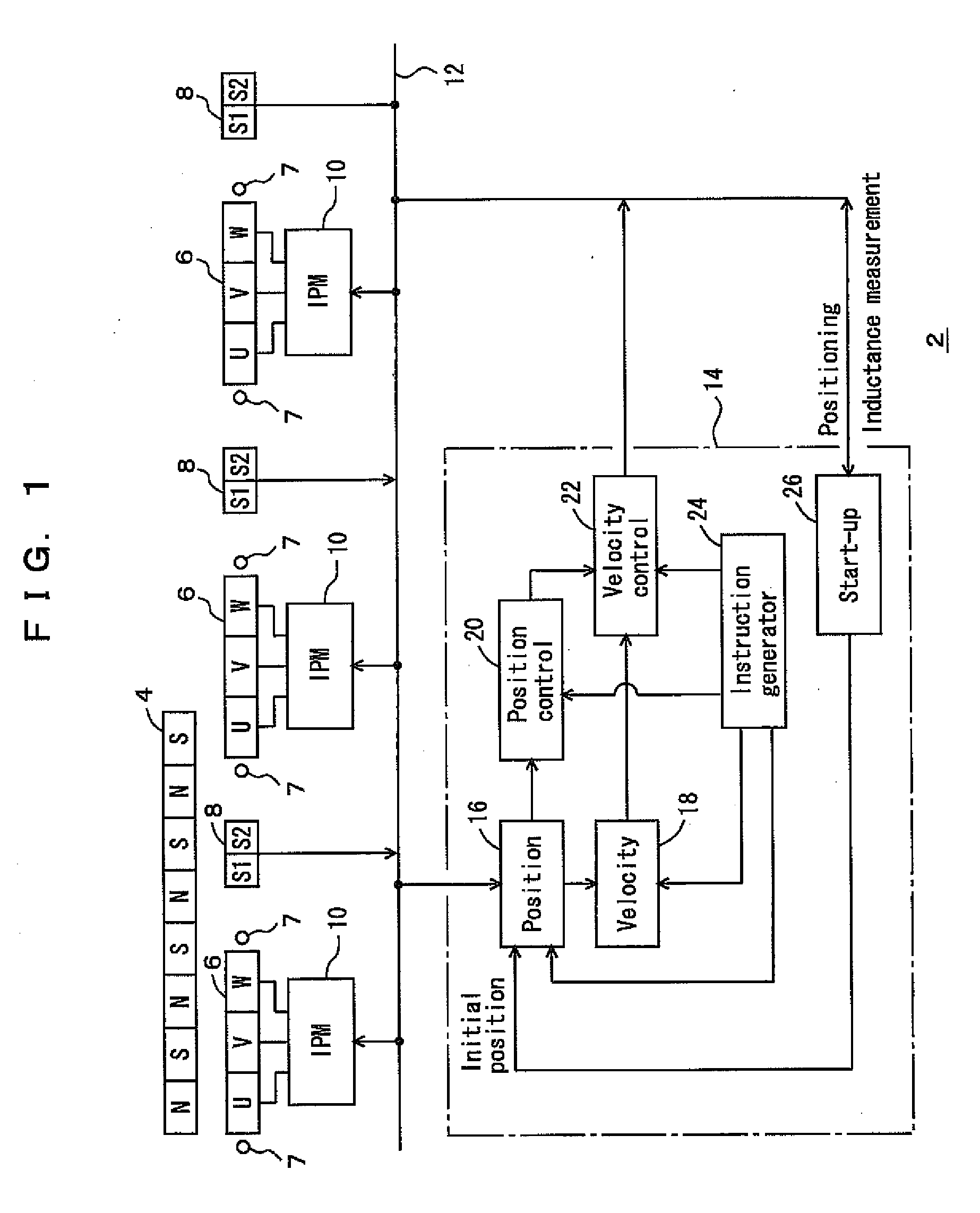
[0027]FIGS. 1 to 7 show a moving body system 2 according to a preferred embodiment of the present invention and various modifications thereof. In the drawings, a reference numeral 4 denotes a movable element of a linear motor provided on a moving body (not shown). For example, the moving body may be a stacker crane, an overhead traveling vehicle, a rail vehicle traveling on the ground, a conveyor, a movable head of machine equipment, etc. The number of magnetic poles of the movable element 4, i.e., the number of magnetic poles oriented to a stationary element is, e.g., 6 to 11. Reference numerals 6 denote stationary elements of the linear motor. The ...


PUM


Abstract

In a moving body system, a movable element of a linear motor is provided on a moving body, and stationary elements of the linear motor and position sensors are provided on the ground. The stationary elements are arranged between the position sensors to enable determination of a rough position of the movable element based on a change of inductance resulting from interaction with a magnet array. An initial position of the moving body when a power supply for the moving body system is turned on is determined based on the rough position of the movable element relative to the stationary element and a signal from the position sensor.

Description

BACKGROUND OF THE INVENTION[0001]1. Field of the Invention[0002]The present invention relates a moving body system including a linear motor having a primary side on the ground and a secondary side on a moving body. In particular, the present invention relates to a technique of measuring an initial position of the moving body, e.g., at the time of a start-up operation of the system.[0003]2. Description of the Related Art[0004]JP2007-82307A discloses a technique of controlling a linear motor by providing a movable element of the linear motor on a moving body such as a stacker crane, providing stationary elements of the linear motor on the ground, and detecting a position of the moving body using linear sensors. The stationary elements are provided discretely, and the linear sensors are provided discretely to determine the position of the moving body based on a signal from a linear sensor detecting the moving body.[0005]In this regard, in general, the movable element is made up of a pl...

Claims


Application Information

Patent Timeline
Patent Type & Authority Applications(United States)
IPC IPC(8): H02K41/02
CPCH02P3/24H02P6/006H02P2207/05H02P6/186H02P21/0053H02P6/183H02P21/32
Inventor KUBO, HIDEKI
Owner MURATA MASCH LTD
Why Eureka
Try Eureka