Buck converter and method for providing a current for at least one LED

a technology of buck converter and led, which is applied in the direction of electric variable regulation, process and machine control, instruments, etc., can solve the problems of often too expensive integrated circuits for mass production, and achieve the effect of speeding up the clearance of the base of the buck main switch

Active Publication Date: 2011-03-03
LEDVANCE GMBH
View PDF13 Cites 27 Cited by
  • Summary
  • Abstract
  • Description
  • Claims
  • Application Information

AI Technical Summary

Benefits of technology

[0021]Preferably, the control electrode and the reference electrode of the third auxiliary switch have a capacitor coupled between them. This is used to keep down the base potential of the third auxiliary switch when the conducting states change from the first auxiliary switch to the third auxiliary switch (influence of the switching times of the Buck diode, of the first auxiliary switch and of the second auxiliary switch), such that the third auxiliary switch and hence the Buck main switch remain safely off during the demagnetization of the Buck inductor to the desired minimum current.
[0022]Finally, it is preferred if the control electrode of the Buck main switch is coupled to the first input connection via a nonreactive resistor. This speeds up the clearance of the base of the Buck main switch, provided that the latter is in the form of a bipolar transistor.

Problems solved by technology

However, such integrated circuits are frequently too expensive for use in mass products.

Method used


Image

  • Buck converter and method for providing a current for at least one LED
  • Buck converter and method for providing a current for at least one LED

Examples


Embodiment Construction

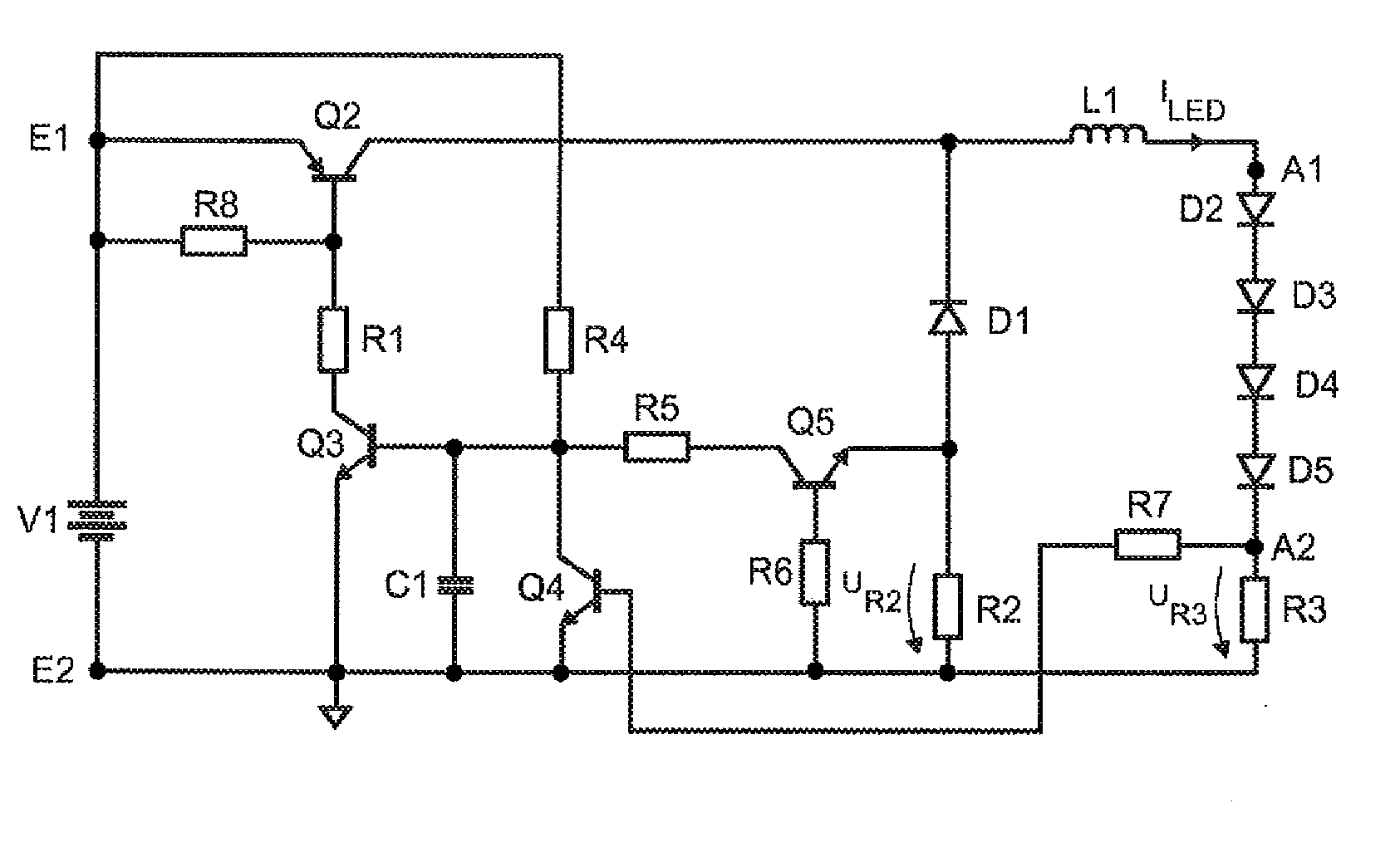
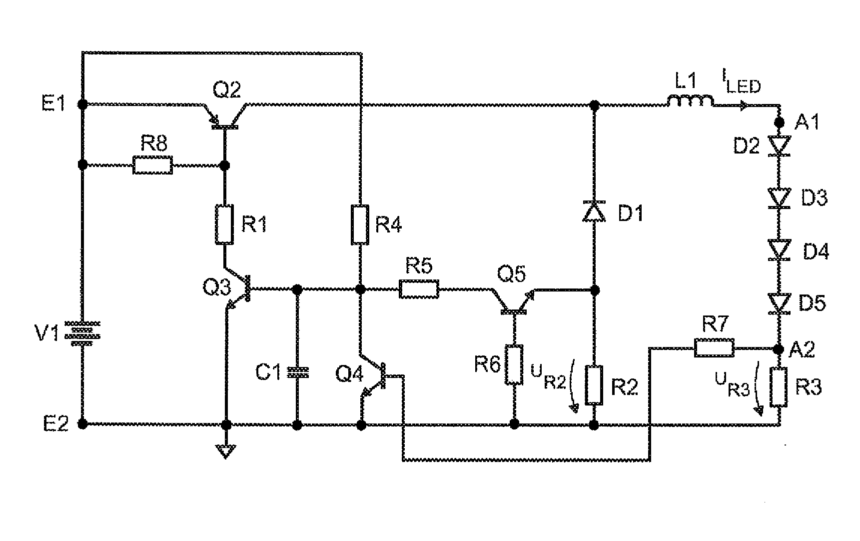
[0026]FIG. 1 shows a schematic illustration of an exemplary embodiment of a Buck converter according to the invention. This has an input with a first input connection E1 and a second input connection E2, between which a low-voltage DC voltage source V1 at, in the present case, 9 V is coupled. The input connection E2 is coupled to a reference potential. The first input connection E1 and the second input connection E2 have the series circuit comprising a Buck main switch Q2, a Buck diode D1 and a nonreactive resistor R2 coupled between them. The connecting point for the Buck main switch Q2 and the Buck diode D1, on the one hand, and a first output connection A1 have a Buck inductor L1 coupled between them. The output connection A1 and a second output connection A2 have an LED, which in the circuit diagram is represented by the series circuit including D2, D3, D4 and D5, coupled between them. The output connection A2 and the reference potential have a non-reactive resistor R3 coupled b...


PUM


Abstract

A Buck converter may include an input for connecting a DC voltage source; an output for connecting an LED; and a diode, an inductor and a main switch; wherein the diode and the main switch are coupled in series, wherein the inductor is coupled between the connecting point for the diode and the main switch, and a first output connection, wherein the converter further includes: a first auxiliary switch supplied with a first voltage; and a second auxiliary switch supplied with a second voltage, wherein the first auxiliary switch and the second auxiliary switch are coupled to the main switch such that the first voltage stipulates the switch-off time for the main switch and the second voltage stipulates the switch-on time for the main switch.

Description

TECHNICAL FIELD[0001]The present invention relates to a Buck converter for providing a current for at least one LED having an input with a first input connection and a second input connection for connecting a DC voltage source, an output with a first output connection and a second output connection for connecting the at least one LED, and the Buck diode, a Buck inductor and a Buck main switch, which has a control electrode, a working electrode and a reference electrode. Furthermore, it relates to an appropriate method for providing a current for at least one LED using a Buck converter.PRIOR ART[0002]With the advance of LEDs into broad areas of general lighting, there is a great need for simple and inexpensive power supply circuits for these components. There are now a large number of, in particular, integrated circuits which have been designed for such demands. Merely by way of example, the LM3402 chips from the National company and the LT3474 chip from the Linear Technology company...

Claims


Application Information

Patent Timeline
Patent Type & Authority Applications(United States)
IPC IPC(8): H05B41/36H05B44/00
CPCH05B33/0815H05B45/375H02M3/1563Y02B20/30
Inventor RUDOLPH, BERND
Owner LEDVANCE GMBH
Why Eureka
Try Eureka