Wireless transmission system, wireless communication device, and wireless communication method

a wireless communication and wireless communication technology, applied in the field of wireless communication devices, wireless communication systems, wireless communication methods, etc., can solve the problems of system size problems, inconvenient high-speed communication, and easy interference between wireless signals and baseband signals, so as to facilitate synchronous detection and relax the stability of modulation carrier signals , the effect of improving data transmission ra

Active Publication Date: 2011-03-03
SONY CORP
View PDF38 Cites 62 Cited by
  • Summary
  • Abstract
  • Description
  • Claims
  • Application Information

AI Technical Summary

Benefits of technology

[0012]However, in the case of considering realization of wireless high-speed signal transmission between pieces of electronic apparatus disposed at a comparatively-short distance and in electronic apparatus by a frequency band corresponding to shorter wavelengths (e.g. millimeter wave band), it would appear that it is not wise to require the carrier frequency to have high stability. Rather, it would appear that it is better to consider relaxing the stability of the carrier frequency to thereby use an oscillator circuit having a simple circuit configuration and simplify the system configuration as a whole.
[0026]Because the stability of the frequency of the carrier signal may be relaxed, the whole of the oscillator circuit including a tank circuit (and a frequency converter) can be formed on the same semiconductor substrate. A one-chip oscillator circuit (semiconductor integrated circuit) including a built-in tank circuit and a one-chip communication circuit (semiconductor integrated circuit) including a built-in tank circuit are realized.

Problems solved by technology

Thus, this system is not suitable for high-speed communication for e.g. video signal transmission.
In addition, this system has size problems such as a large antenna size.
Therefore, this system also involves a problem that interference readily occurs between the wireless signal and the baseband signal.
Moreover, when the carrier frequency is low, the transmission is susceptible to the influence of driving system noise in the apparatus and countermeasures thereagainst are necessary.
This means that an oscillator circuit having high frequency stability but a complicated circuit configuration is necessary, and means that the system configuration as a whole also becomes complicated.
Furthermore, in the case of attempting to realize the whole of the oscillator circuit including a tank circuit (resonant circuit composed of inductors and capacitors) by a silicon integrated circuit, in practice, it is difficult to form a tank circuit having a high quality factor and thus a tank circuit having a high quality factor has to be disposed outside the integrated circuit.

Method used


Image

  • Wireless transmission system, wireless communication device, and wireless communication method
  • Wireless transmission system, wireless communication device, and wireless communication method
  • Wireless transmission system, wireless communication device, and wireless communication method

Examples


first embodiment

5. Injection Locking System: First Embodiment

6. Injection Locking System: Second Embodiment

7. Configuration Example of Oscillator Circuit

[0063]8. Relationship between Multi-channel Transmission and Injection Locking

9. Transmission Path Structure (for Transmission in Housing and between Mounted / Loaded Pieces of Apparatus)

10. System Configuration: First Application Example (Single Channel)

11. System Configuration: Second Application Example (Broadcast Communication)

12. System Configuration: Third Application Example (Frequency Division Multiplexing: Two Channels)

13. System Configuration: Fourth Application Example (Frequency Division Multiplexing: Full-duplex Bidirectional Communication)

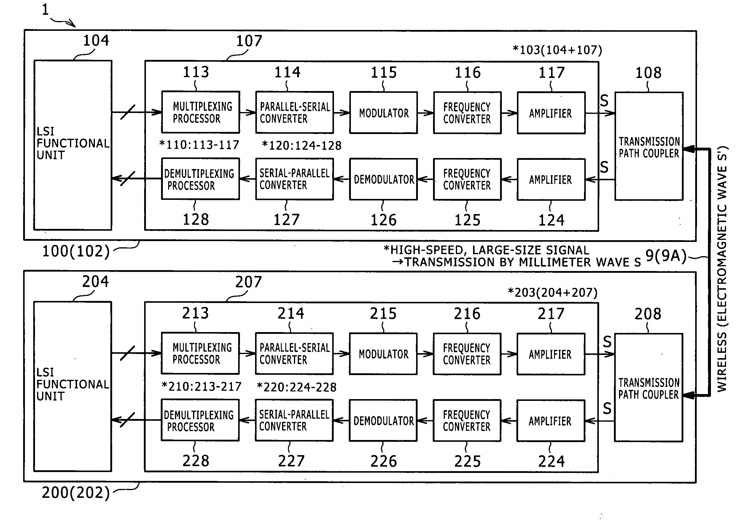
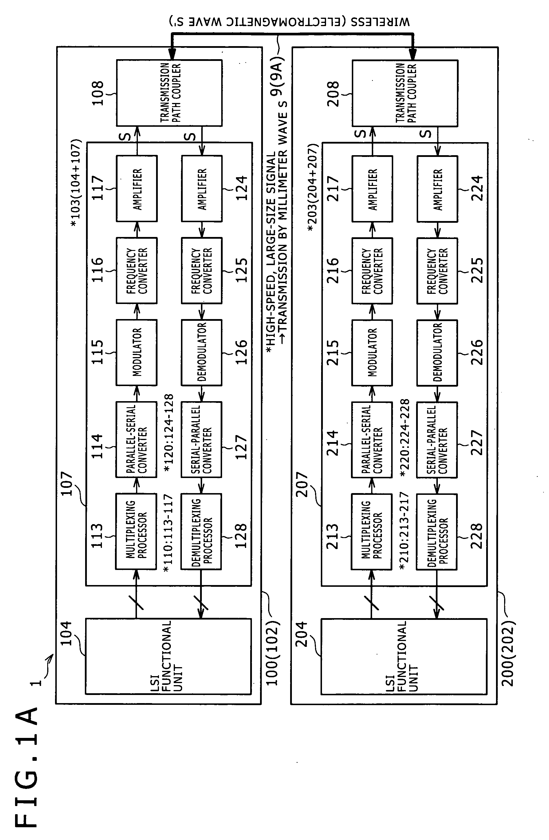
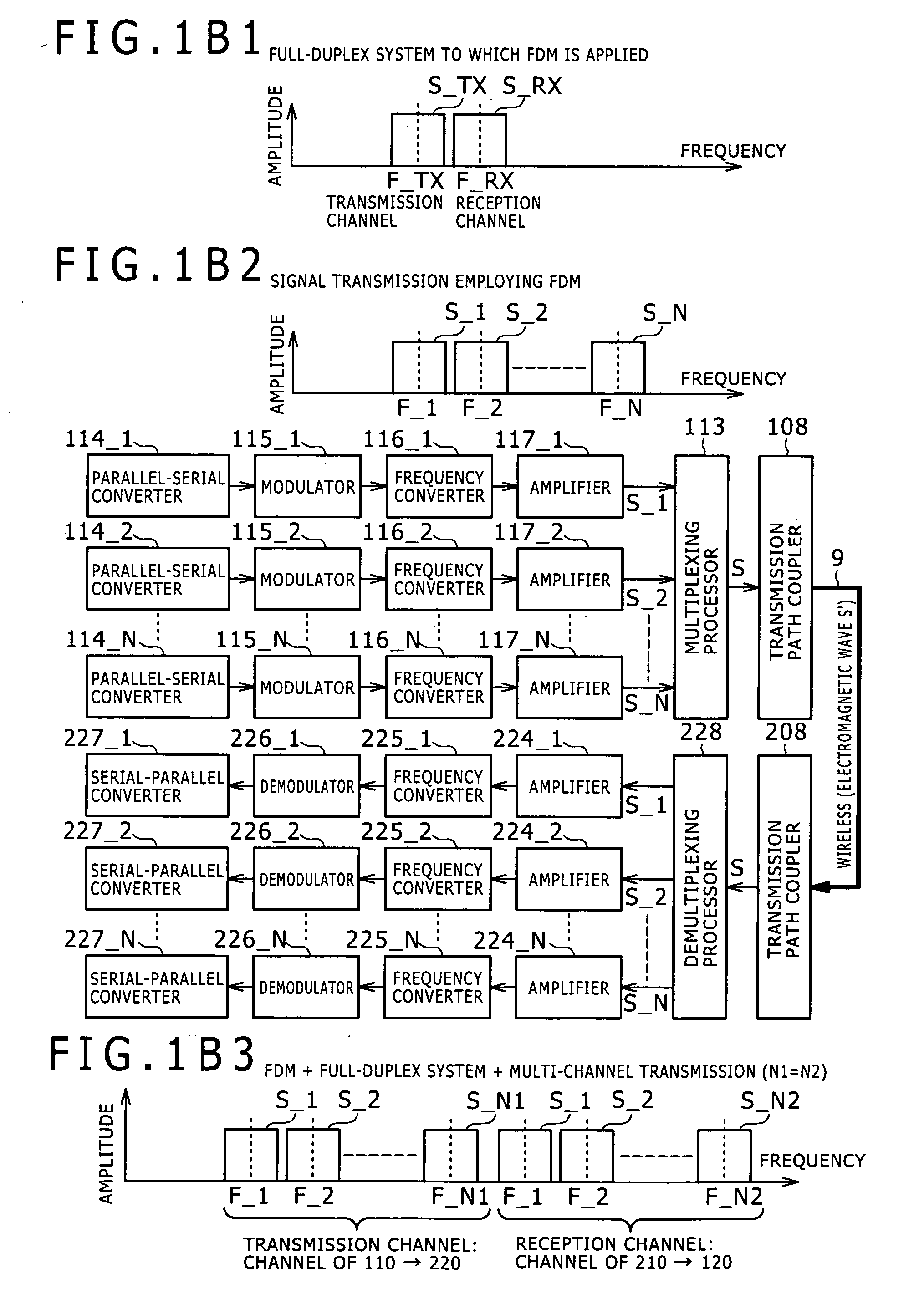
[0064]FIGS. 1A to 1B3 are diagrams for explaining a wireless transmission system according to the embodiments of the present invention. Specifically, FIG. 1A is a diagram for explaining the signal interface of a wireless transmission system 1 in terms of the functional configuration. FIGS. 1B1 to 1B3 a...

first example

[0321]FIGS. 13A1 to 13A5 are diagrams for explaining a first example of the wireless transmission path structure of the embodiments. The transmission path structure of the first example is an application example in which signal transmission is performed by millimeter waves in the housing of one piece of electronic apparatus. In this application example, an imaging device including a solid-state imaging device is employed as the electronic apparatus.

[0322]This imaging device has a system configuration in which the first communication device 100 is mounted on the main board on which a control circuit, an image processing circuit, and so forth are mounted and the second communication device 200 is mounted on an imaging board on which the solid-state imaging device is mounted. In FIGS. 13A1 to 13A5, a schematic sectional view of an imaging device 500 is shown with focus on millimeter-wave signal transmission between the boards, and diagrammatic representation of parts having no relation...

second example

[0345]FIGS. 13B1 to 13B3 are diagrams for explaining a second example of the wireless transmission path structure of the embodiments. The transmission path structure of the second example is an application example in which signal transmission is performed between pieces of electronic apparatus by millimeter waves in the state in which the plural pieces of electronic apparatus are integrated with each other. For example, this second example is application to signal transmission between two pieces of electronic apparatus when one piece of electronic apparatus is mounted on the other piece of electronic apparatus (e.g. on the main body side).

[0346]For example, there is a system in which a card-type information processing device typified by so-called IC card and memory card in which a central processing unit (CPU), a nonvolatile memory device (e.g. flash memory), and so forth are incorporated is allowed to be (detachably) mounted in electronic apparatus on the main body side. The card-t...


PUM


Abstract

A wireless transmission system includes: a communication unit for transmission; and a communication unit for reception. The communication units for transmission and reception are housed in a housing of the same electronic apparatus, or the communication unit for transmission is housed in a housing of first electronic apparatus and the communication unit for reception is housed in a housing of second electronic apparatus and a wireless signal transmission path enabling wireless information transmission between the communication units is formed between the communication units when the first and the second electronic apparatus are disposed at given positions to be integrated with each other. The communication unit for transmission includes a first carrier signal generating unit and a first frequency converter, and the communication unit for reception includes a second carrier signal generating unit, and a second frequency converter.

Description

BACKGROUND OF THE INVENTION[0001]1. Field of the Invention[0002]The present invention relates to a wireless transmission system, a wireless communication device, and a wireless communication method.[0003]2. Description of the Related Art[0004]For example, low voltage differential signaling (LVDS) is known as a technique for realizing high-speed signal transmission between pieces of electronic apparatus disposed at a comparatively-short distance (e.g. within several centimeters to ten and several centimeters) and high-speed signal transmission in electronic apparatus. However, along with recent further increases in the size and transmission speed of transmission data, increase in the power consumption, increase in the influence of signal distortion due to reflection and so forth, increase in unnecessary radiation, etc. become problems. For example, the performance of the LVDS is reaching the limit in the case of high-speed (real-time) transmission of e.g. video signals (including ima...

Claims


Application Information

Patent Timeline
Patent Type & Authority Applications(United States)
IPC IPC(8): H04B1/00
CPCH04B1/40H04L27/04H04L27/122H04L27/20H04L27/365
Inventor KAWASAKI, KENICHI
Owner SONY CORP
Why Eureka
Try Eureka