Stack/folding-typed electrode assembly and method for preparation of the same

a technology of stacking type and electrode assembly, which is applied in the direction of cell components, sustainable manufacturing/processing, flat cell grouping, etc., can solve the problems of deteriorating battery performance, reducing productivity, and requiring a great deal of time and effort to perform sequential stacking process, so as to improve battery performance and simplify the manufacturing process. , the effect of improving the productivity of the battery

Active Publication Date: 2011-03-03
LG ENERGY SOLUTION LTD
View PDF7 Cites 56 Cited by
  • Summary
  • Abstract
  • Description
  • Claims
  • Application Information

AI Technical Summary

Benefits of technology

[0053]According to the method of manufacturing the electrode assembly, on the other hand, as will be described below, the full cells are arranged in the same electrode orientation such that the top electrodes of the respective full cells located after the second stage of the separator sheet have a polarity opposite to the bottom electrode of the unit electrode or the bi-cell located at the first stage of the separator sheet. Consequently, it is not necessary to change the electrode orientation of the full cells, which are the unit cells. That is, it is possible to place the full cells on the separator sheet in the same electrode orientation and then wind the full cells, whereby the manufacturing process is simplified, and therefore, the productivity of the battery is improved. Also, as previously described, it is possible to solve the problem in that the performance of the battery is deteriorated due to errors during the manufacture of the battery.
[0054]In an exemplary example, the method may further include attaching the unit electrode or the bi-cell and the full cells placed at step 2) to the separator sheet before the winding, thereby easily achieving the winding of the cells on the separator sheet. The attachment may be achieved, preferably, by thermal welding. For example, the lamination may be easily achieved at low glass transition temperature (TG). A solution obtained by dissolving polymer, such as PVDF, HFD, PMMA, PEO, or PMMA, which is electrochemically stable at a potential range of 0 to 5 V in a predetermined solvent is applied to a separator and is then dried to manufacture a separator sheet coated with a coupling agent. Subsequently, the unit electrode and the cells are placed on the separator sheet, and then predetermined pressure and heat are applied to the unit electrode, the cells, and the separator sheet. The coupling agent-coated separator sheet may be used as the separator of each cell. The coupling agent-coated separator sheet may assist to maintain the stack structure of the full cells by its coupling force with respect to the electrodes during the manufacture of the electrode assembly

Problems solved by technology

First, the jelly-roll type electrode assembly is manufactured by densely winding the long-sheet type cathodes and the long-sheet type anodes with the result that the jelly-roll type electrode assembly is circular or elliptical in section. Consequently, stress, caused by the expansion and contraction of the electrodes during the charge and discharge of a battery, accumulates in the electrode assembly, and, when the stress accumulation exceeds a specific limit, the electrode assembly may be deformed. The deformation of the electrode assembly results in the nonuniform gap between the electrodes. As a result, the performance of the battery is abruptly deteriorated, and the safety of the battery is not secured due to an internal short circuit of the battery. Furthermore, it is difficult to rapidly wind the long-sheet type cathodes and the long-sheet type anodes while maintaining uniformly the gap between the cathodes and anodes, with the result that the productivity is lowered.
Secondly, the stack type electrode assembly is manufactured by sequentially stacking the plurality of unit cathodes and the plurality of unit anodes. As a result, it is additionally necessary to provide a process for transferring electrode plates, which are used to manufacture the unit cathodes and the unit anodes. Furthermore, a great deal of time and effort are required to perform the sequential stacking process, with the result that the productivity is lowered.
In order to stack the bi-cells or the full cells, which are the unit cells, such that the bi-cells or the full cells have opposite electrodes at the interfaces between the unit cells, however, it is required to sort the bi-cells or the full cells based on the type of the bi-cells or the full cells and load the bi-cells or the full cells on the separator sheet according to a predetermined rule, with the result that the manufacturing process is complicated and troublesome, and therefore, the productivity is lowered.
Furthermore, it is very complicated and troublesome to sort the unit cells based on the type of the unit cells.
Consequently, when even any one of the unit cells is omitted or wrongly located due to various causes, such as carelessness or errors, during loading the unit cells on the separator sheet, electrodes having the same polarity face each other at the interfaces between the unit cells, with the result that the performance of the battery is deteriorated.
However, the stack / folding type electrode assembly is disadvantageous as described above in the aspect of the productivity of the battery.
Also, the large-sized battery module requires a long-term life span property.

Method used


Image

  • Stack/folding-typed electrode assembly and method for preparation of the same
  • Stack/folding-typed electrode assembly and method for preparation of the same
  • Stack/folding-typed electrode assembly and method for preparation of the same

Examples


first embodiment

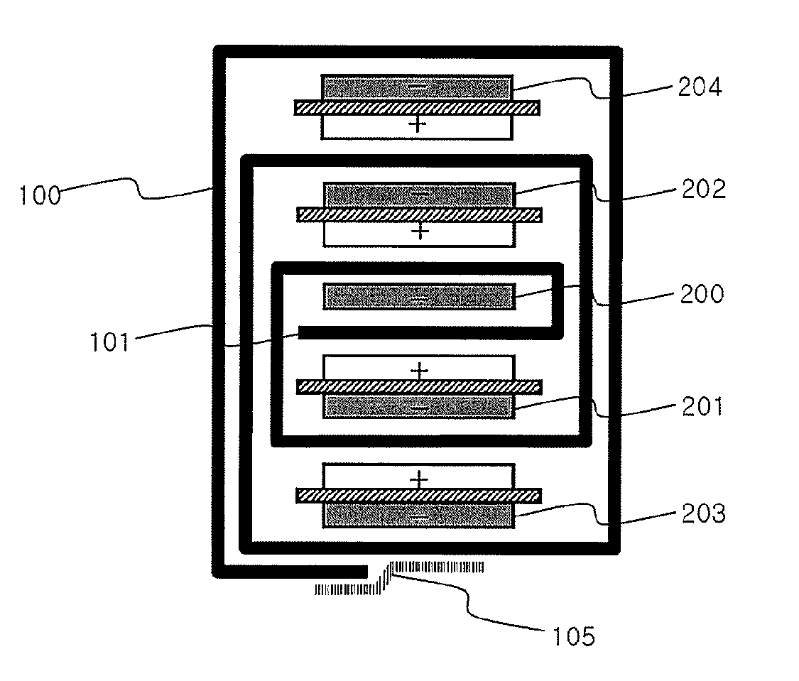
[0074]First, FIG. 4 illustrates the structure of an electrode assembly according to the present invention in which an anode 200 is located at the middle of the electrode assembly, which is a winding start point 101. Full cells 202 and 204 above the anode 200 and full cells 201 and 203 below the anode 200 are arranged in a symmetrical structure.

second embodiment

[0075]Next, FIG. 5 illustrates the structure of an electrode assembly according to the present invention in which a cathode 300 is located at the middle of the electrode assembly, which is a winding start point 101. As in FIG. 4, full cells 302 and 304 above the cathode 300 and full cells 301 and 303 below the cathode 300 are arranged in a symmetrical structure. The bottommost cell 303 and the topmost cell 304, which form the outer surface of the electrode assembly, may be full cells (not shown) which are arranged in a symmetrical structure. Alternatively, the bottommost cell 303 and the topmost cell 304 may be formed of A-type bi-cells in which anodes occupy a large area to maximally restrain the dendritic growth at the anodes.

[0076]FIGS. 6 to 8 are typical views illustrating processes for manufacturing electrode assemblies using unit electrodes and full cells in accordance with various embodiments of the present invention, respectively.

[0077]Referring to these drawings, a separato...


PUM

PropertyMeasurementUnit
thicknessaaaaaaaaaa
pore diameteraaaaaaaaaa
lengthsaaaaaaaaaa

Abstract

Disclosed herein is an electrode assembly constructed in a structure in which a plurality of electrochemical cells, formed of full cells having a cathode/separator/anode structure, as basic units, are overlapped, and a continuous separator sheet is disposed between the overlapped electrochemical cells, wherein a unit electrode surrounded by the separator sheet is located at a middle of the overlapped electrochemical cells, which is a winding start point, and the full cells disposed above and below the unit electrode are symmetrical to each other about the unit electrode in the direction of electrodes of the full cells. The electrode assembly is manufactured with high productivity while the electrode assembly exhibits performance and safety equal to those of a conventional stack/folding type electrode assembly.

Description

FIELD OF THE INVENTION[0001]The present invention relates to a method of manufacturing a stack / folding type electrode assembly and a method of manufacturing the same, and, more particularly, to an electrode assembly constructed in a structure in which a plurality of electrochemical cells, formed of full cells having a cathode / separator / anode structure, as basic units, are overlapped, and a continuous separator sheet is disposed between the overlapped electrochemical cells, wherein a unit electrode surrounded by the separator sheet is located at a middle of the overlapped electrochemical cells, which is a winding start point, and the full cells disposed above and below the unit electrode are symmetrical to each other about the unit electrode in the direction of electrodes of the full cells.BACKGROUND OF THE INVENTION[0002]As mobile devices have been increasingly developed, and the demand for such mobile devices has increased, the demand for batteries has also sharply increased as an ...

Claims


Application Information

Patent Timeline
Patent Type & Authority Applications(United States)
IPC IPC(8): H01M2/20H01M50/417H01M50/463H01M50/489H01M50/491
CPCH01M2/1653H01M2/1673H01M2/18H01M10/0459Y10T29/49108H01M10/0583Y02T10/7011Y02E60/122H01M10/0525H01M50/46H01M50/463H01M50/417H01M50/491H01M50/489Y02P70/50Y02E60/10H01M50/50H01M50/20H01M50/10Y02T10/70
Inventor KIM, KIJAEKIM, MIN SU
Owner LG ENERGY SOLUTION LTD
Why Eureka
Try Eureka