Methods for stable sequestration of carbon dioxide in an aquifer

a carbon dioxide and aquifer technology, applied in the direction of separation process, transportation and packaging, borehole/well accessories, etc., to achieve the effect of stable sequestration, large percentage, and stable sequestration

a carbon dioxide and aquifer technology, applied in the direction of separation process, transportation and packaging, borehole/well accessories, etc., to achieve the effect of stable sequestration, large percentage, and stable sequestration

US20110056373A1Active Publication Date: 2011-03-10U S BANK TRUST CO NAT ASSOC

Image

  • Methods for stable sequestration of carbon dioxide in an aquifer
  • Methods for stable sequestration of carbon dioxide in an aquifer
  • Methods for stable sequestration of carbon dioxide in an aquifer

Examples


Embodiment Construction

I. Introduction

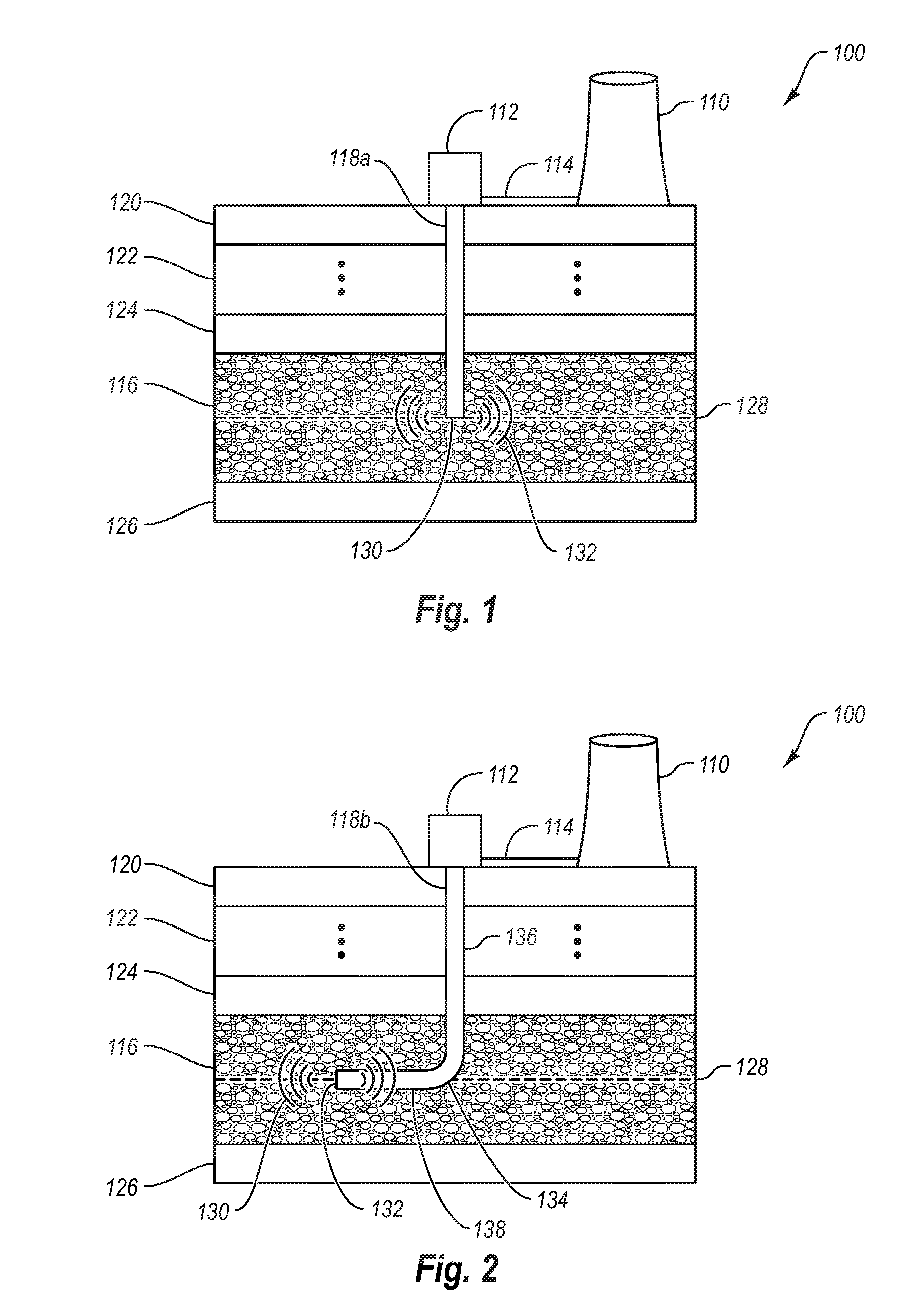
[0023]The methods disclosed herein relate to sequestering carbon dioxide in an aquifer by trapping the CO2 in interstitial pores of the aquifer in addition to dissolving the CO2 in the fluid. Trapping the CO2 in the interstitial pores of the aquifer stabilizes the CO2 from essential the time of injection, preventing the sequestered CO2 from escaping back to the surface, and greatly increases the storage capacity of the aquifer compared to fluid dissolution alone.

[0024]For purposes of this invention, a “CO2 stream” as used herein refers to a fluid with a substantially higher concentration (e.g., greater than 1.0 vol %) of carbon dioxide compared to “naturally existing” atmospheric air, which has less than about 0.04 vol % carbon dioxide. However, in most cases a much higher concentration of CO2 is desired do avoid the expense associated with sequestering gases other than CO2.

[0025]For purposes of the present invention, the term “horizontal well” refers to a well shaft ...


PUM

PropertyMeasurementUnit
Fractionaaaaaaaaaa
Fractionaaaaaaaaaa
Angleaaaaaaaaaa

Abstract

The methods disclosed herein relate to sequestering carbon dioxide in an aquifer by trapping the CO2 in interstitial pores of the aquifer. Trapping the CO2 in the interstitial pores of the aquifer prevents the sequestered CO2 from escaping back to the surface and allows a much larger percentage of a CO2 to be stably sequestered compared to techniques that rely on dissolving the CO2 to achieve stable sequestration.

Description

CROSS-REFERENCE TO RELATED APPLICATIONS[0001]This application is a continuation of PCT Application serial number PCTUS2009 / 036089, entitled METHODS FOR STABLE SEQUESTRATION OF CARBON DIOXIDE IN AN AQUIFER filed Mar. 4, 2009, which claims the benefit of U.S. Provisional Application No. 61 / 068,129, filed on Mar. 4, 2008, entitled FOSSIL AND BIOMASS POWER SYSTEMS WITH STABLE CO2 SEQUESTRATION both of which are hereby incorporated herein by reference in their entirety1. THE FIELD OF THE INVENTION[0002]The present invention relates to methods for sequestering carbon dioxide in an aquifer.2. THE RELEVANT TECHNOLOGY[0003]The need to control CO2 emissions on a global scale is widely recognized. Electric power generation plants, which combust fossil fuels to create power, provide an excellent opportunity to mitigate man-made CO2 emissions. In North America, coal is the primary fuel used for electric power generation.[0004]One of the control strategies proposed for CO2 capture / sequestration i...

Claims


Application Information

Patent Timeline
10 Mar 2011
Publication
US20110056373A1
IPC
B01D53/14
CPC
B01D53/62; B01D2257/504; Y02C10/14; E21B41/0064; Y02C10/04; B65G5/005; Y02P70/10; Y02A50/20
Inventors
BAXTER, LARRY L.