[0007]The present invention seeks to overcome or reduce at least some of the above-described problems with the prior art. More particularly, the present invention desires to maintain and improve on the existing methods and validators' reliability of discriminating between real and false banknotes, whilst at the same time seeking to reduce costs of such discriminating systems.
[0013]The whole point of the present invention is to apply this discovery at a low cost. Whilst it would be possible to use a spectrophotometer, this is clearly too expensive as it is several orders of magnitude greater in price that the banknote
validator itself. Rather, the present invention is embodied in a simple, light source, sensor and
optical filter arrangement, which minimises cost. It is to be appreciated that a high-pass or a low-pass filter, namely a filter having a simple step function, is typically far cheaper than a band-pass filter. Also the present invention can be implemented with a single sensor if needs be rather than two sensors as is seen in EP 0 738 408. Furthermore, the computational overhead of validating a genuine banknote is significantly reduced as compared with the prior art devices, because a single integrated reading for each different part of the banknote to be sensed is obtained rather than multiple different readings at each banknote sensing location. Furthermore, and very importantly, the use of a
broadband sensor is key to keeping the cost of the present invention low. This is because a single
broadband sensor is cheaper than a narrow band sensor or multiple sensors.
[0015]The present invention accords with the above-mentioned desire and specifically provides a method and validator that can discriminate a very large variety of different types of false banknotes from real banknotes at a very low
relative cost with a minimum number of sensors and sensor arrangements. Sensors that have a broadband sensing characteristic are a far lower cost than narrow-band sensing characteristic sensors, which helps to reduce costs. Also by simplifying the sensor arrangement, the reliability of the validator increases and the amount of data generated decreases as does, very importantly, its costs.
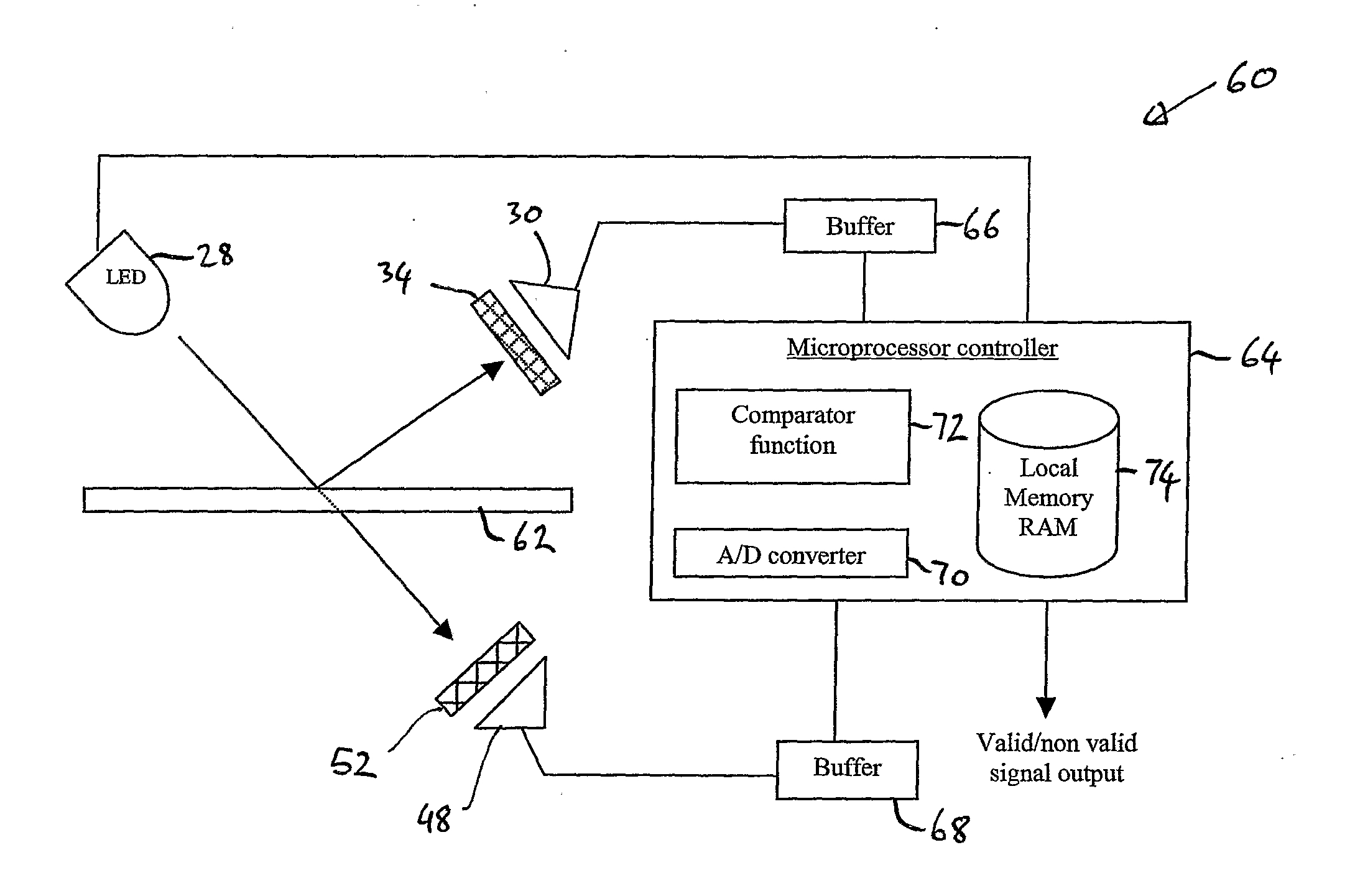
[0019]In one embodiment of the present invention, the banknote can be first excited (irradiated with non-visible light) at low cost by using an
ultraviolet emitting LED (light-emitting
diode). However, by using a broadband optical
receiver with in conjunction with a high-pass wavelength (low-pass frequency) optical filter, higher wavelength emissions can be detected. This can be created using a general-purpose low-cost
photodiode and a low-cost conventional plastics filter. The
photodiode has a broad response but the high-pass filter cuts off at 500 nm or at a point at least greater than the highest wavelength emitted from the excitation light source. The filter separates out the light that is reflected back from the banknote that does not cause any excitation from the other low-level florescence wavelengths.
[0020]The use of a single sensor also makes the task of making the comparison between a valid and a false banknote easier, because the single sensor integrates the emitted responses over a wide range of wavelengths which in turn results in a single
voltage output
signal being produced representing a value for that banknote location. Once several such values have been obtained they can be compared against reference values representative of a valid banknote. In the actual validation of a banknote, a whole banknote would need to be read by taking a plurality of readings at different positions with the single sensor and comparing all the results with reference voltages. Using the present embodiment, for each point on the banknote, a single integrated multiple wavelength reading is taken rather than multiple readings with different optical wavelengths. A single value for a banknote location can be used for comparison instead of the prior art method of carrying out more complex analysis on multiple results for each banknote location.
[0021]The main benefit of this
system is that it provides much better recognition of real banknotes compared to false banknotes than the previously known visible ‘blue’ emission based systems. Furthermore, the present invention is also significantly lower in cost to manufacture and is simpler than other systems that necessarily require more than one sensor for measuring each of the reflected and
transmitted light interactions.

